combustible dust, fibers, or paper and remove any for-
eign materials. Contact your local Hyster dealer for
forklift modifications that may be appropriate in envi-
ronments with fire hazards.
Operate the lift truck only in areas that have been
approved for lift truck operation.
• OSHA regulations prohibit the use of lift trucks in
areas containing hazardous concentrations of cer-
tain flammable gases or vapors.
• OSHA regulations require operating areas to be clas-
sified as hazardous or nonhazardous, and that the
lift trucks used in designated locations be of the
minimum type specified (see Guide For Users Of
Industrial Trucks, Appendix C and Table N-1).
Only the designated types of approved lift trucks may
be used in areas classified as hazardous by the author-
ity having jurisdiction. Areas classified as hazardous
must be identified by signs to show the type of
approved lift truck required for operation in the area.
Modifications or poor maintenance can result in the lift
truck being unsuitable for operation in areas classified
as hazardous.
The fork lift truck is designed to pickup, move, and tier
materials. The basic lift truck has a lift mechanism and
forks on the front to engage the load. The lift mechanism
lifts the load so that it can be moved and stacked.
In order to understand how the fork lift truck can pick up a
load, you must first know some basic things about the lift
truck.
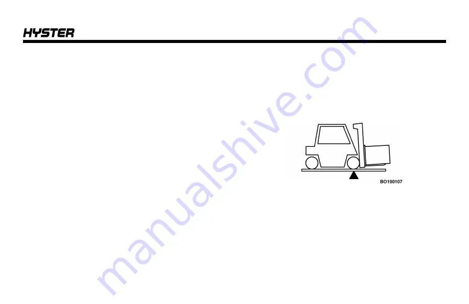
The lift truck is based on the principle of two weights bal-
anced on opposite sides of a pivot (fulcrum). This is the
same principle used for a seesaw. In order for this principle
to work for a lift truck, the load on the forks must be bal-
anced by the weight of the lift truck. The location of the
center of gravity of both the truck and the load is also a fac-
tor.
Operating Procedures
49
Summary of Contents for H40-60XT
Page 1: ...OPERATING MANUAL H40 60XT A380 DO NOT REMOVE THIS MANUAL FROM THIS UNIT PART NO 4150900 3 19...
Page 11: ...Model Description Figure 1 Model View Showing Major Components of H40 60XT Model Description 9...
Page 16: ...Figure 3 Warning and Safety Labels Sheet 1 of 3 Model Description 14...
Page 17: ...Figure 3 Warning and Safety Labels Sheet 2 of 3 Model Description 15...
Page 18: ...Figure 3 Warning and Safety Labels Sheet 3 of 3 Model Description 16...
Page 20: ...Figure 4 Controls Model Description 18...
Page 42: ...Figure 5 Dash Display Warning and Indicator Lights Model Description 40...
Page 62: ...Figure 6 Seat Adjustment Operating Procedures 60...
Page 90: ...1 DRIVE TIRES 2 STEERING TIRES Figure 10 Put a Lift Truck on Blocks Maintenance 88...
Page 92: ...Figure 11 Maintenance and Lubrication Points PSI 2 4L LPG Trucks Maintenance Schedule 90...
Page 94: ...Figure 13 Maintenance and Lubrication Points PSI 2 4L Bi Fuel Trucks Maintenance Schedule 92...
Page 115: ...Figure 16 Seat Check Maintenance 113...
Page 120: ...1 FRAME 2 PDM 3 GROUND STATIC STRAP 4 BATTERY Figure 18 Ground Static Strap Maintenance 118...
Page 137: ...Figure 30 Brake Fluid Reservoir Cover Maintenance 135...
Page 139: ...Figure 31 PDM Showing Fuses and Relays Maintenance 137...
Page 178: ...NOTES 176...
Page 179: ...Spacer 3 19 12 18 7 18 12 17 10 17 5 17 3 17 1 17 11 16 10 16 7 16 5 16 4 16 3 16...
Page 180: ...OPERATING MANUAL H40 60XT A380 DO NOT REMOVE THIS MANUAL FROM THIS UNIT PART NO 4150900 3 19...


