General Information About Diagrams and Schematics
The chassis wiring used in these vehicles conforms
to the electrical circuit identification standard
ES-1359 and in addition to surface marked ID
circuit numbers, generally utilizes the colors that
are indicated in Table 1.
MONOTROL
®
, engine harnesses, wiring to sensors,
and other applications vary with respect to wire
colors.
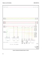
Diagrams and schematics in this manual can be
viewed and printed in color.
If not printed or viewed in color, refer to the
electrical circuit identification located on schematic
circuits. When viewing a color version of the
diagrams and schematics, the white chassis wires
are seen as yellow. Other wires are shown in colors
similar to actual colors, i.e. tan shows as yellow.
Use circuit identification for true wire color.
Refer to Diagnostic Troubleshooting Manual
9000SRM1112 Section 9030, Group 03 - General
Maintenance and Diagnostic Data, for further
information.
Table 1. Wire Colors
Color
Use/Function
Red
Battery-level power circuits and 5 volt supply
circuits
Black
Heavy current grounds
Green
Signal grounds
White
Other circuits
Twisted Pair (Yellow/Green) Yellow Green
CANbus CAN-Hi CAN-Lo
Twisted Pair (Dk Blue/Pink and Dk Blue/White) Dk
Blue/Pink Dk Blue/White
CANbus (Mazda) CAN-Hi CAN-Lo
Letter on the VSM BUS
Use/Function
R
Regulated Output Voltage
D
Driver
I
Input
8000 SRM 1904
General Information About Diagrams and Schematics
1
Summary of Contents for J004
Page 5: ...THE QUALITY KEEPERS HYSTER APPROVED PARTS...
Page 11: ...Figure 1 Electrical Schematic Sheet 2 of 45 8000 SRM 1904 Diagrams and Schematics 5...
Page 12: ...Figure 1 Electrical Schematic Sheet 3 of 45 Diagrams and Schematics 8000 SRM 1904 6...
Page 13: ...Figure 1 Electrical Schematic Sheet 4 of 45 8000 SRM 1904 Diagrams and Schematics 7...
Page 14: ...Figure 1 Electrical Schematic Sheet 5 of 45 Diagrams and Schematics 8000 SRM 1904 8...
Page 15: ...Figure 1 Electrical Schematic Sheet 6 of 45 8000 SRM 1904 Diagrams and Schematics 9...
Page 16: ...Figure 1 Electrical Schematic Sheet 7 of 45 Diagrams and Schematics 8000 SRM 1904 10...
Page 17: ...Figure 1 Electrical Schematic Sheet 8 of 45 8000 SRM 1904 Diagrams and Schematics 11...
Page 18: ...Figure 1 Electrical Schematic Sheet 9 of 45 Diagrams and Schematics 8000 SRM 1904 12...
Page 19: ...Figure 1 Electrical Schematic Sheet 10 of 45 8000 SRM 1904 Diagrams and Schematics 13...
Page 20: ...Figure 1 Electrical Schematic Sheet 11 of 45 Diagrams and Schematics 8000 SRM 1904 14...
Page 21: ...Figure 1 Electrical Schematic Sheet 12 of 45 8000 SRM 1904 Diagrams and Schematics 15...
Page 22: ...Figure 1 Electrical Schematic Sheet 13 of 45 Diagrams and Schematics 8000 SRM 1904 16...
Page 23: ...Figure 1 Electrical Schematic Sheet 14 of 45 8000 SRM 1904 Diagrams and Schematics 17...
Page 24: ...Figure 1 Electrical Schematic Sheet 15 of 45 Diagrams and Schematics 8000 SRM 1904 18...
Page 25: ...Figure 1 Electrical Schematic Sheet 16 of 45 8000 SRM 1904 Diagrams and Schematics 19...


