background image

MAINTENANCE

NARROW AISLE

59

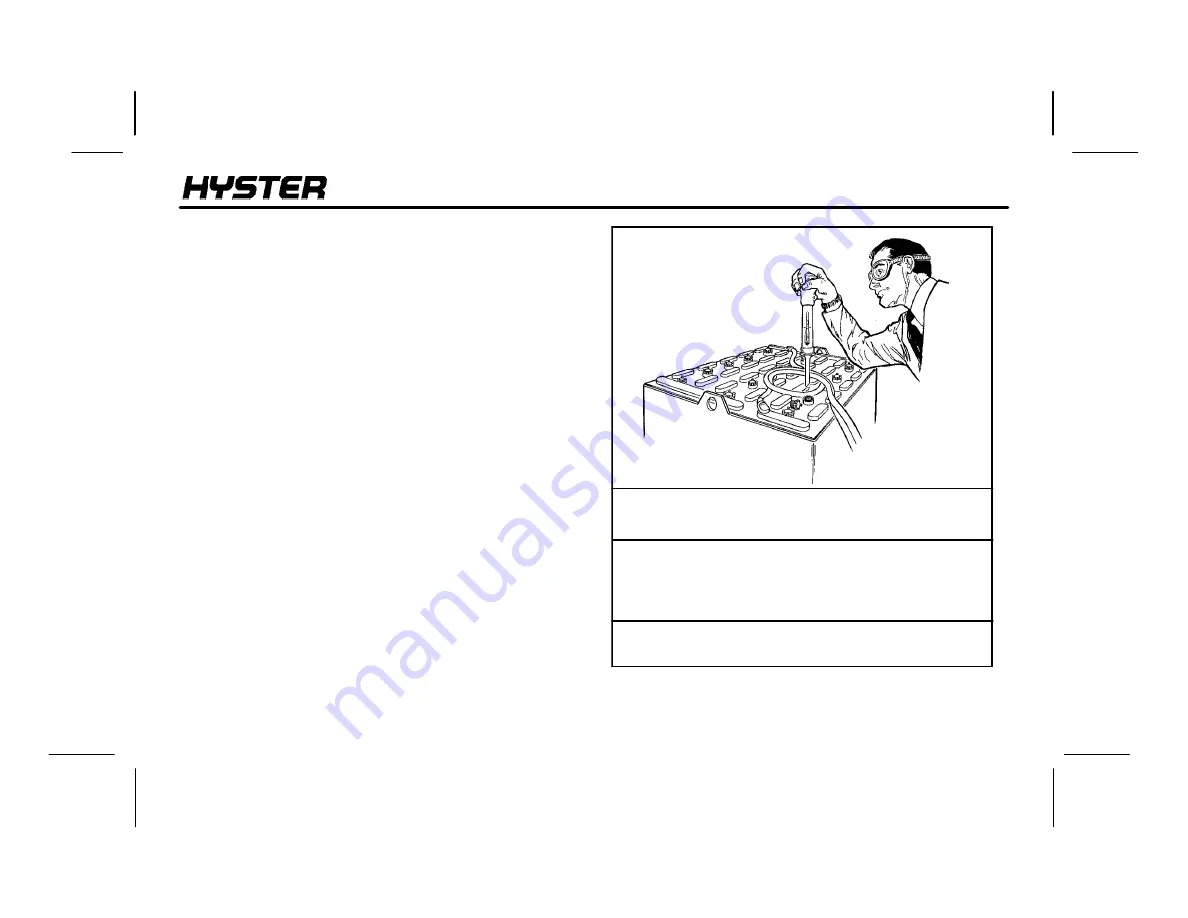
Correct use of the hydrometer and proper operation of the
battery charger is important. Follow the instructions of the
charger manufacturer. Never let the battery discharge
below the minimum value given by the battery
manufacturer. A fully charged battery will have a specific
gravity of 1.265 to 1.310 at 25

°

C (77

°

F). Never charge a

battery at a rate that will raise the electrolyte temperature
above 49

°

C (120

°

F). Do not let a battery stay discharged

for a long period of time.

1. Normal Charge:

This charge is normally given to a

battery that is discharged from normal operation. Many
customers charge the battery at regular intervals that
depend on use. This procedure will keep the battery
correctly charged if the battery is not discharged below the
limit. Always use a hydrometer to check the battery if the
battery is charged at regular intervals. Frequent charging of
a battery that has a two-thirds (2/3) or more charge can
decrease the life of the battery.

2. Equalizing Charge:

Is a low rate charge and

balances the charge in all the cells. The equalizing charge
is given approximately once a month. It is a charge at a slow
rate for three to six hours in addition to the regular charging
cycle. Do not give an equalizing charge more than once a
week.

+0.001 or --0.001 for each 2

°

C

from the 25

°

C base value.

FIGURE 13. CHECK SPECIFIC GRAVITY

SPECIFIC

GRAVITY

1.210

1.210

1.210

1.210

ELECTROLYTE

TEMPERATURE

31

°

C (87

°

F)

27

°

C (80

°

F)

25

°

C (77

°

F)

18

°

C (64

°

F)

CORRECTION

POINTS

+0.003

+0.001

0.000

--0.004

CORRECT

VALUE

1.213

1.211

1.210

1.206

Property of American Airlines

Summary of Contents for Narrow Aisle N25XMDR3

Page 1: ...OPERATING MANUAL 12 05 1487036 DO NOT REMOVE THIS MANUAL FROM THIS UNIT NARROW AISLE N30 40XMR3 N25XMDR3 C470 N50XMA3 C471 N45XMR3 N30XMDR3 G138 P r o p e r t y o f A m e r i c a n A i r l i n e s ...

Page 2: ...R LIFT HEIGHT GROUP NUMBER DRIVE TIRE SIZE COMPOSITION SPECIAL EQUIPMENT OR ATTACHMENTS REGISTERED TRADEMARKS Hyster SpaceSaver Straddle Truck Karry Krane Yardmaster Monotrol OrderMaster SpaceMaster RACKLOADER SitDrive and StanDrive are registered trademarks of Hyster Company P r o p e r t y o f A m e r i c a n A i r l i n e s ...

Page 3: ...ure that the operator can see hear and has the physical and mental ability to operate the equipment safely Various laws and regulations require the employer to train lift truck operators These laws and regulations include Occupational Safety and Health Act OSHA USA Canada Material Handling Regulations NOTE A comprehensive operator training program is available from HYSTER COMPANY For further detai...

Page 4: ... government insurers private insurers and private organizations Example Accident Prevention for Industrial Operations from the National Safety Council S Guide for Users of Industrial Lift Trucks describes lift truck safety good maintenance practices and training programs Available from your dealer for HYSTER lift trucks HYSTER part number 852930 NOTE HYSTER lift trucks are not intended for use on ...

Page 5: ... TO MOVE A DISABLED LIFT TRUCK 42 How to Tow the Lift Truck 42 How to put a Lift Truck on Blocks 43 MAINTENANCE PROCEDURES 50 CHECKS WITH THE KEY SWITCH OFF 50 Hydraulic System 50 Forks 51 Reach Tilt and Sideshift 54 Articulation Stop Adjustment 54 Battery 55 CHECKS WITH THE KEY SWITCH ON 56 Gauges Horn and Fuses 56 Control Levers and Pedals 56 Lift System Operation 56 Brake 57 HOW TO CHARGE THE B...

Page 6: ...CONTENTS 4 NOTES P r o p e r t y o f A m e r i c a n A i r l i n e s ...

Page 7: ... S Make sure tailswing area is clear before turning S Sound horn at intersections or wherever vision is blocked S Watch clearances especially overhead KNOW YOUR LOADS S Handle only stable loads within specified weight and load center See nameplate on this truck S Space forks as far apart as load allows and center load between forks S Keep load against load backrest S Do not handle loose loads high...

Page 8: ...ff power Block wheels on inclines PROTECT YOURSELF S Avoid bumps holes loose materials and slippery areas S Avoid sudden starts or stops Operate all controls smoothly S Never turn on or angle across an incline Travel slowly S Travel on inclines with load uphill or unloaded with mast downhill S Tilt slowly and smoothly Lift and lower with mast or carriage vertical or tilted slightly back Use minimu...

Page 9: ...pt hourmeters LED function selection lights operator selectable drive modes for speed of traction and an LCD display which provides the status of systems and fault messages in English not in numerical codes All lift trucks have operator protection equipment The overhead guard is intended to offer reasonable protection to the operator from falling objects but cannot protect against every possible i...

Page 10: ... truck nameplate already has a capacity for special load handling equipment it will be listed Make sure the nameplate data is complete and fully understood before operating the lift truck The lift truck serial code number is on the nameplate The serial code number is also stamped on the lift truck frame FIGURE 1 NAMEPLATE NOTICE TO USER The U S A Occupational Safety and Health Act of 1970 and othe...

Page 11: ...el Multi Function Handle 13 Label Fork Warning 14 Label Overhead Guard 15 Label Pinch Points 16 Label Articulation 17 Label Identification EE 18 Label Freezer Identification 19 Operating Manual 10 Label Manual Lowering 11 Label Underwriters Laboratory 12 Label Cooler Identification P r o p e r t y o f A m e r i c a n A i r l i n e s ...

Page 12: ...MODEL DESCRIPTION NARROW AISLE 10 FIGURE 4 WARNING LABELS P r o p e r t y o f A m e r i c a n A i r l i n e s ...

Page 13: ...IFT TRUCK Major Components of the Lift Truck 1 2 4 5 7 9 8 1 Overhead Guard 2 Mast 3 Load Backrest 4 Forks 5 Basearms 6 Battery Compartment 7 Drive Steer Wheel 8 Load Wheels 9 Operator s Compartment 10 Carriage 6 3 10 P r o p e r t y o f A m e r i c a n A i r l i n e s ...

Page 14: ...MODEL DESCRIPTION NARROW AISLE 12 FIGURE 6 INSTRUMENTS AND CONTROLS P r o p e r t y o f A m e r i c a n A i r l i n e s ...

Page 15: ...ghts The instrument display is powered even when the vehicle is not being operated When the battery is disconnected the dashboard contains an internal back up battery capable of memory retention of the battery indicator and hourmeter WARNING If any of the instruments or controls do not operate as described in this table report the problem immediately DO NOT operate the lift truck until the problem...

Page 16: ...eived the warning fault indicator will blink as a yellow light When a fault message is received the warning fault indicator will blink as a red light The Function Selection Lights display the selected hydraulic function Status messages will be displayed for LIFT REACH TILT AND SIDESHIFT The function selection lights will display the current hydraulic function independent of the present LCD display...

Page 17: ...o select the traction motor controller speed most suited to the application Operation of the drive mode switch will cause the green indicators and corresponding drive modes to increase from Turtle to Mid to Rabbit Turtle mode provides slower acceleration and reduced top speed It is also a valuable setting when training new operators or on wet floors for better traction Mid mode reduces acceleratio...

Page 18: ...motor hours Press four times to return to the normal display mode If the hourmeter is left in any of the first three positions the display will return to the normal display mode which indicates the current operational status of the lift truck after 30 seconds Hourmeter 2 Operating Manual e The Operating Manual is sent with the lift truck and is located in the container on the wire mast guard mount...

Page 19: ...use The brake is spring applied and hydraulically released The push down brake pedal is on the floor in the rear of the operator s compartment The brake is automatically applied when the brake pedal is released An operator sensing switch is on the floor to the right of the brake pedal and must be closed with the brake pedal switch before lift truck operation is permitted The operator must step int...

Page 20: ...he lift truck Power is restored to the lift truck by pulling the switch upward Battery Power Disconnect 7 The steering disk controls lift truck direction with 4 turns lock to lock WARNING Reverse steering is available for this lift truck The operator should check the steering direction before operating the lift truck Steering Disk P r o p e r t y o f A m e r i c a n A i r l i n e s ...

Page 21: ...arther the control handle is pushed the faster the lift truck will accelerate or decelerate If the multi function handle is released it will return to neutral and the truck will decelerate at a programmed rate to a stop The multi function handle controls the direction and speed at which the carriage moves vertically on the mast Lift Lower is activated by tilting the entire control handle toward th...

Page 22: ... the right side of the disk to move the carriage to the right Tilt and sideshift are single speed functions The Extend and Retract buttons are located on the shaft of the multi function handle Press the top button to provide low speed extend While the top button is still actuated press the bottom button to provide high speed extend Press the bottom button to provide low speed retract While the bot...

Page 23: ...t of the total lift truck weight The location of the center of gravity of both the lift truck and the load is also a factor This basic principle is used to pick up a load The ability of the lift truck to handle a load is discussed in terms of center of gravity and stability Stability and Center of Gravity The center of gravity CG of any object is the single point about which the object is balanced...

Page 24: ...h its load in the lowered position In order for the lift truck to be stable not tip over forward or to the side the CG must stay within the area of the lift truck represented by a triangle drawn between the load wheels and the pivot of the steering axle CG Truck Will Tip Over Load Wheel Axle Steering Axle Pivot If the CG moves forward of the load wheels the lift truck will tip forward If the CG mo...

Page 25: ...n attachment to the center of gravity of the load Both the vertical and horizontal load centers Loads should be transported while centered on the centerline of the lift truck The operator must know whether or not a load is within the maximum capacity of the lift truck before the load is handled WARNING Inspect the lift truck and check the operation of the systems at the start of the day or shift D...

Page 26: ... only do its job when it is in proper working order If repairs are required install a tag in the operator s area stating DO NOT OPERATE and remove the key from the key switch How to Check the SRO Circuit The lift truck is equipped with a Static Return to OFF SRO circuit that prevents travel of the lift truck if the starting sequence is not correct The function of the SRO circuit is to make sure th...

Page 27: ... as it tips over CAUTION If the lift truck is stationary during a check release the brake pedal and proceed carefully Check the operation of the following functions as described in the MAINTENANCE section S Check the operation of the horn gauges and indicator lights S Operate the lift tilt reach and auxiliary functions to check for correct operation of the mast carriage and attachments S Check the...

Page 28: ...t a qualified person experienced in lift truck operation must guide the operator through several driving and load handling operations before the operator attempts to operate the lift truck alone A basic education in proper driving and load handling techniques is absolutely necessary to prepare the new operator for proper defensive driving and to expect the unexpected 2 Hazardous Area Operate the l...

Page 29: ...make sure the mast functions properly Apply the park brake Do not travel with people in the platform The operator must remain at the controls Watch for over head obstructions 5 Elevators Do not drive a lift truck into a elevator unless authorized to do so Approach the elevator slowly After the elevator is properly leveled the lift truck must be centered so that the elevator is balanced When the li...

Page 30: ... place at any travel speed The lift truck will come to a stop and then accelerate in the opposite direction Plugging is a normal method used to stop the lift truck and is proportional to how much the control handle is moved in the opposite direction To stop the lift truck quickly step off the brake pedal to apply the brake Steering Turning WARNING Travel slowly when turning Lift trucks can tip ove...

Page 31: ...work in a relatively small space they can turn sharper than some other vehicles Most lift trucks are steered by the rear wheels and the rear of the lift truck can move to the side very fast during a turn This movement is called tailswing An operator must be aware of tailswing and always check to make sure the tailswing area is clear before turning TAILSWING When turning the lift truck from a wide ...

Page 32: ...tance from the center of the carriage This action will help center the load on the carriage Set the forks as far apart as possible for maximum support of the load Center the weight of the load between the forks If the weight of the load is not centered between the forks the load can fall from the forks when you turn a corner or hit a bump An off center load will increase the possibility of the tru...

Page 33: ... objects but cannot protect against every possible impact A lift truck with out an overhead guard provides no such protection and other personnel have no overhead protection Avoid hit ting objects such as stacked material that could become dislodged and fall Avoid hitting objects such as stacked material that could become dislodged and fall The operator must exercise care while working near such o...

Page 34: ...ard with a load in the raised position How to Engage and Disengage a Load 1 Avoid fast starts Sudden movement can cause the lift truck to tip People can be hurt or killed and material can be damaged Approach the load carefully Make sure that the truck is perpendicular to the load Raise the forks to the proper height for engaging the load 2 Move forward slowly or ex tend the forks slowly until the ...

Page 35: ...l of the forks Carefully move the lift truck backward to remove the forks from under the load If the forks are longer than the load move the forks under the load so that the tips of the forks do not extend beyond the load Lift the load from the surface Move backward or retract forks a few inches then lower the load onto the surface and inch forward or extend forks to engage the load against the ca...

Page 36: ...he neutral position so that the load is not dropped or that the lift truck is not tipped over due to the rapid stop of the load 5 To put the load on a stack align the lift truck with the stack Lift the load to eye level and then tilt the load forward until it is level Raise the load higher than the point where it will be placed Do not raise the load to a point below where the load is to be placed ...

Page 37: ...st fully backward to help keep the load on the forks Traveling 1 When traveling with the load lowered keep the load against the carriage the forks retracted and the forks tilted fully backward This action will help keep the load on the forks and give good forward and side stability 2 Travel with the lift mecha nism raised only enough to clear the ground base arms or ob stacles When any part of the...

Page 38: ...imes Do not drive up close to anyone standing in front of an object Use extra care at cross aisles doorways and other locations where pedestrians can step into the path of travel of the lift truck Slow down when approaching blind intersections or turns Sound the horn to warn pedestrians that there is a vehicle in the area and to be alert to possible danger 6 Anytime the lift truck is moving keep a...

Page 39: ...f unavoid able slow down 10 Do not pass another lift truck traveling in the same direction at intersections blind spots or at other dangerous locations 11 Stay away from the edge of the road Keep the wheels of the lift truck particularly the steer wheels on the roadway If the wheels are allowed to run off the edge of the travel surface onto soft ground the lift truck can tip over 12 Under all trav...

Page 40: ...n can cause the lift truck to fall off the dock Make sure that the railroad car brakes are set and the wheels are blocked while loading or unloading Do this so that the railroad car will not move due to the movement of the lift truck in and out of the railroad car When entering a railroad car the operator can enter at an angle if the dock plate or bridge is wide enough This will reduce the turning...

Page 41: ... a condition so that it can cause damage and injury When parking the lift truck do the following operations 1 Bring the lift truck to a stop Release the control handle so that it returns to the neutral position 2 Release the brake pedal to apply the brake 3 Fully lower the forks or carriage Fully retract the forks Tilt the forks forward 4 Turn the key switch to OFF If the lift truck is parked beca...

Page 42: ...OPERATING PROCEDURES NARROW AISLE 40 NOTES P r o p e r t y o f A m e r i c a n A i r l i n e s ...

Page 43: ...iciently and operate over a longer period of time Some users have service personnel and facilities to do the items listed in the MAINTENANCE SCHEDULE Service Manuals are available from your HYSTER lift truck dealer to help users who do their own maintenance Maintenance service and repair must be performed by trained personnel Do not make repairs or adjustments unless specifically authorized to do ...

Page 44: ...a load center equal to half the width of the disabled lift truck See the nameplate of the disabled lift truck for the approximate total weight The forks must extend the full width of the disabled lift truck Center the weight of the disabled lift truck on the forks and be careful not to damage the under side of the lift truck How to Tow the Lift Truck 1 The towed lift truck must have an operator 2 ...

Page 45: ... only if the surface is solid even and level Make sure that any blocks used to support the lift truck are solid one piece units WARNING Do not raise the lift truck by attaching an overhead crane to the overhead guard or areas of the mast that will be damaged Some of these components and oth er lift points are not designed to support the weight of the lift truck The truck can be damaged or it can f...

Page 46: ...ear of the frame to support the lift truck How to Raise the Load Wheels See FIGURE 8 1 Release the brake pedal to apply the brake Put blocks on both sides front and back of the drive steer tire and the caster wheels to prevent movement of the lift truck 2 Use an overhead crane and web sling under the base arms at the mast to raise the load wheels Another lift truck can also be used to raise the ba...

Page 47: ...MAINTENANCE NARROW AISLE 45 Load Wheels Drive Steer and Caster Wheels FIGURE 8 PUTTING THE LIFT TRUCK ON BLOCKS P r o p e r t y o f A m e r i c a n A i r l i n e s ...

Page 48: ...MAINTENANCE NARROW AISLE 46 FIGURE 9 MAINTENANCE POINTS 1 1 3 2 4 5 8 9 12 2 10 13 15 17 16 14 7 11 6 4 4 6 8 15 6 3 13 P r o p e r t y o f A m e r i c a n A i r l i n e s ...

Page 49: ...k Operation Check Operation Replace See Specifications Bearings Seal 5 Forks All Hook Fork Guides and Locks X X L Check for Damage As Required Anti Seize Lubricant3 6 Gauges Horn Lights Fuses X Check Operation X Check C Change L Lubricate 1 Hydraulic Oil Hyster P N 131820 6 Multi Purpose Grease with 2 4 Molybdenum Disulfate 2 Chevron EP Hydraulic Oil 68 or equivalent for normal operations Hyster P...

Page 50: ... Retaining Bolt Articulation Shaft Ends L L L 1 Lube Fitting Multi Purpose Grease6 Anti Seize Lubricant3 Anti Seize Lubricant3 12 Reach Arms N30 40 45XMR3 Reach Arms N25 30 XMDR3 Reach Cylinder Pivot Pins Thrust Rollers Reach Frame X L L L L 6 Lube Fittings 12 Lube Fittings 4 Lube Fittings 2 Lube Fittings Multi Purpose Grease6 Multi Purpose Grease6 Multi Purpose Grease6 Multi Purpose Grease6 X Che...

Page 51: ...6 gal Multi Purpose Grease6 Multi Purpose Grease6 SAE 80W 90 or Mobilgear 627 SAE 80W 90 or Mobilgear 627 Anti Seize Lubricant3 17 Drive Wheel Bolt Torque Drive Wheel Lugs X L Tighten if Required 135 NSm 100 lbf ft Anti Seize Lubricant3 X Check C Change L Lubricate 1 Hydraulic Oil Hyster P N 131820 6 Multi Purpose Grease with 2 4 Molybdenum Disulfate 2 Chevron EP Hydraulic Oil 68 or equivalent for...

Page 52: ...ck the hydraulic oil level when the oil is at operating temperature the carriage is lowered the reach mechanism retracted and the key switch is in the OFF position Table 2 Hydraulic Oil Tank Capacities BATTERY COMPARTMENT SIZE OIL TANK CAPACITY TO FULL MARK 318 mm 12 5 in 21 6 litres 5 70 gal 371 mm 14 6 in 23 5 litres 6 22 gal 422 mm 16 6 in 25 5 litres 6 73 gal 478 mm 18 8 in 29 3 litres 7 74 ga...

Page 53: ... the carriage or use chains on the mast weldments and carriage so that they cannot move Make sure the mov ing parts are attached to a part that does not move See the PERIODIC MAINTENANCE section WARNING Do not try to lift a fork without a lifting device On some trucks the forks can weigh up to 180 kg 400 lb each Adjust the forks as far apart as possible for maximum support of the load Hook forks a...

Page 54: ...hims Never repair damaged forks by heating or welding Forks are made of special steel us ing special procedures Replace damaged forks 1 Inspect the welds on the mast and carriage for cracks Make sure that the nuts and bolts are tight 2 Inspect the channel for excessive wear in the areas of roller contact Check the rollers for wear or damage 3 Inspect the load backrest extension for cracks and dama...

Page 55: ...d pins 1 Tip Alignment Must be within 3 of Fork Length 2 Cracks 3 Latch Damage 4 Heel of Fork Must be 90 of Dimension X 5 Heel Wear FIGURE 12 CHECK THE FORKS FORK TIP ALIGNMENT Length of Forks 914 mm 36 in 1067 mm 42 in 1220 mm 48 in 3 Dimension 27 mm 1 10 in 32 mm 1 16 in 37 mm 1 44 in 1 2 X 3 5 4 9 Inspect the chain anchors and pins for cracks and damage P r o p e r t y o f A m e r i c a n A i r...

Page 56: ...e 3 Check the load backrest extension for cracks and damage Make sure that the nuts and bolts for the load backrest extension are tight Articulation Stop Adjustment The articulation stop screws must be adjusted to the proper setting as listed on the nameplate and in the Articulation Chart at the following times 1 Every 350 hours during routine maintenance 2 When a drive and or caster wheel is chan...

Page 57: ...y Labels WARNING Safety labels are installed on the lift truck to give infor mation about possible hazards It is important that all safety labels are installed on the lift truck and can be read Check that all safety labels are installed in the correct locations on the lift truck See the PARTS MANUAL or the Frame Section of the SERVICE MANUAL for the correct locations of the safety labels Battery C...

Page 58: ... described in Table 1 Check that the brake operates as described in Table 1 Lift System Operation WARNING Never allow anyone under a raised carriage Do not put any part of your body in or through the lift mechanism unless all parts of the mast are completely lowered and the key switch is OFF Before making any repairs put chains on the mast weldments and carriage so that they cannot move Make sure ...

Page 59: ...he lift truck Replace the brake fluid in the system if there is dirt water or oil in the system Check the operation of the brake The brake is applied when the operator removes the foot from the brake pedal The brake pedal can be released slowly to gradually apply the brake The brake when in good condition and correctly adjusted will hold a lift truck with a capacity load on a 15 grade 1 5 meter ri...

Page 60: ...rom the battery connectors WARNING Charge batteries only in a special area for charging batteries When charging the batteries keep the vent caps clean The battery charger area must have venti lation to remove the explosive fumes Open the hood over the battery or remove the cover if the battery has a cover Disconnect the battery when doing cleaning and maintenance WARNING If the lift truck has been...

Page 61: ...ep the battery correctly charged if the battery is not discharged below the limit Always use a hydrometer to check the battery if the battery is charged at regular intervals Frequent charging of a battery that has a two thirds 2 3 or more charge can decrease the life of the battery 2 Equalizing Charge Is a low rate charge and balances the charge in all the cells The equalizing charge is given appr...

Page 62: ... adjusted as described in the following procedure Battery Removal 1 Make sure the key is in the OFF position Disconnect the battery Move the connector and cables so that they will not be damaged when the battery is moved 2 Remove the battery restraint panel from the right hand side of the lift truck 3 Align the battery stand with the battery so that the end of the stand is against the roller frame...

Page 63: ...s are welded To check the contacts see the Main tenance Manual for this truck 1 Make sure that the battery voltage and weight of the replacement battery is correct as shown on the nameplate 2 Install the battery puller on the lift truck frame at the center of the battery compartment on the side opposite the battery stand Release the ratchet lock pass the hook through the battery compartment and at...

Page 64: ...62 FIGURE 14 CHANGE THE BATTERY Installation Removal 1 Battery Restraint Panel 2 Battery Stand 3 Rollers 4 Battery Puller 5 Ratchet Lock Lever 6 Battery 1 4 2 3 6 2 6 3 4 5 5 P r o p e r t y o f A m e r i c a n A i r l i n e s ...

Page 65: ... 986 787 mm 16 6 38 8 31 in 415 986 782 mm 16 35 38 8 30 8 in 771 1089 kg 1700 2400 lb 36 478 986 787 mm 18 8 38 8 31 in 471 986 782 mm 18 55 38 8 30 8 in 998 1293 kg 2200 2850 lb 36 536 986 787 mm 21 1 38 8 31 in 530 986 782 mm 20 85 38 8 30 8 in 1134 1361 kg 2500 3000 lb WARNING The battery must fit the battery compartment so that the battery restraint system will operate correctly Use the space...

Page 66: ... be changed and tires repaired by trained personnel only Always wear safety glasses WARNING The lift truck capacity can change with different types of tires Make sure the capacity on the nameplate is for the type of tires installed on the truck Drive steer tire 1 Raise the rear of the lift truck as described in How to Put a Lift Truck on Blocks 2 Remove the wheel nuts that fasten the drive steer w...

Page 67: ... hours Load Wheels Put the base arms on blocks as described in How to Put a Lift Truck on Blocks For easier installation remove and install one load wheel before removing the next load wheel The load wheel brackets are held in the load arms by the load wheels Remove the axle nut axle and load wheel Remove the axle sleeve from the load wheel Install the new load wheel axle and axle nut 1 Base Arm 2...

Page 68: ...zes TABLE 3 N30 45XMR3 N25 30XMDR3 Tires and Wheels Tire Size Compound Drive Tire 12 5 5 Rubber Drive Tire 12 5 5 Polyurethane Caster 8 2 Polyurethane Load Wheels 5 3 Polyurethane Load Wheels 5 4 Polyurethane TABLE 4 N50XMA3 Tires and Wheels Tire Size Compound Drive Tire 12 5 5 Rubber Drive Tire 12 5 5 Polyurethane Caster 8 2 Polyurethane Load Wheels 4 3 Polyurethane Load Wheels 4 4 Polyurethane P...

Page 69: ...RNING Do not operate the lift truck without the overhead guard correctly fastened to the lift truck Do not make changes to the overhead guard by welding Changes that are made by welding or by drilling holes that are too big or in the wrong location can reduce the strength of the overhead guard See the instructions for Changes to the Overhead Guard in the PERIODIC MAINTENANCE section P r o p e r t ...

Page 70: ...rth defects or other reproductive harm NO MATTER HOW YOU SAY IT La Prudence Paye La Seguridad Paga Betriebssicherheit Macht Sich Bezahlt Passaa Oll Huolellinen Veiligheid Voor Alles Säkerhet Först Essere Sicuro Paga Seguranca Paga Sikkerhet Først Pinter Be Awas 12 05 7 05 8 03 5 01 Litho in U S A P r o p e r t y o f A m e r i c a n A i r l i n e s ...

Page 71: ...OPERATING MANUAL 12 05 1487036 DO NOT REMOVE THIS MANUAL FROM THIS UNIT NARROW AISLE N30 40XMR3 N25XMDR3 C470 N50XMA3 C471 N45XMR3 N30XMDR3 G138 P r o p e r t y o f A m e r i c a n A i r l i n e s ...

Reviews: