6.
On EE units, remove fuse, buss-bar, and stand-
off to access the contactor mounting screws.
7.
Remove two mounting screws located on the
side of the contactor and remove contactor as-
sembly. See Figure 10.
Install
1.
Position contactor assembly in place and install
two mounting screws into the side of the con-
tactor.
2.
On EE units, install stand-off, buss-bar, and
fuse to contactor panel and contactor as re-
moved.
3.
Install wires and cables to the contactor assem-
bly as removed.
4.
Connect the battery, turn the key switch to the
ON position and test for proper operation.
5.
Install the drive unit compartment covers. See
the section Periodic Maintenance
8000SRM1635.
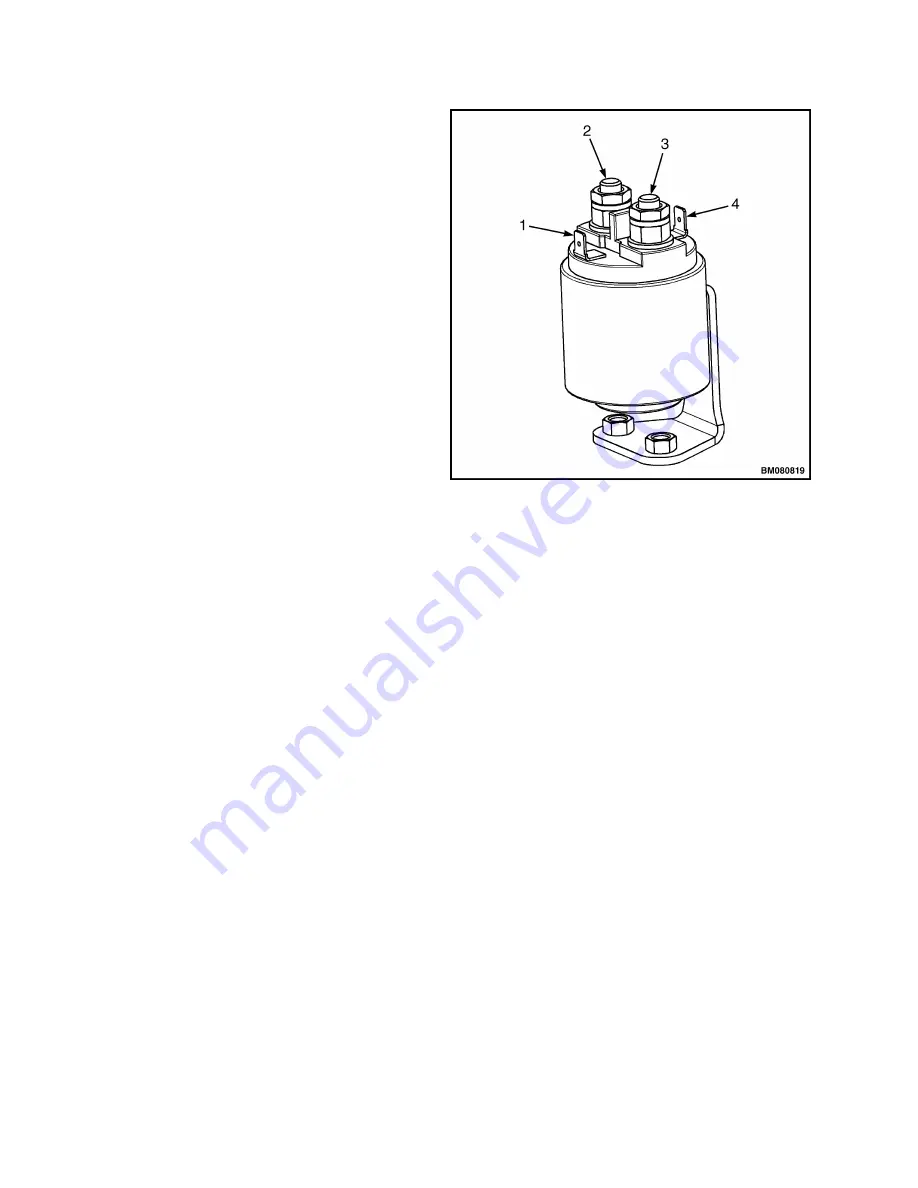
1.
CONTACTOR (TO CONTROLLER)
2.
CONTACTOR (POWER OUT)
3.
CONTACTOR (POWER IN)
4.
CONTACTOR (TO BATTERY POS)
Figure 10. Contactor
Key Switch
REMOVE
Toggle switches may be used in place of key
switches certain applications. The term "key
switch" will be used for both types of switches in
the following instructions. See Figure 11 or Fig-
ure 12.
1.
Move lift truck to a safe area and block drive
wheel to prevent unexpected movement.
2.
Disconnect battery and turn the key switch to
the OFF position.
3.
Remove drive unit compartment covers. See
Periodic Maintenance 8000SRM1635 .
4.
Remove three capscrews holding dash display
to frame mount.
5.
Lift dash display off frame and disconnect wir-
ing from display unit and ignition switch.
6.
Discharge the capacitor. See Special Precau-
tions in this section.
NOTE:
Make note of the orientation of the key
switch for proper installation.
7.
Remove retaining nut from top of the key
switch.
8.
Remove the key switch from mounting hole in
dash display.
9.
Tag and identify all wires and connections for
reference during reassembly. Disconnect wires
from switch.
Repairs
2200 SRM 1632
14


