8
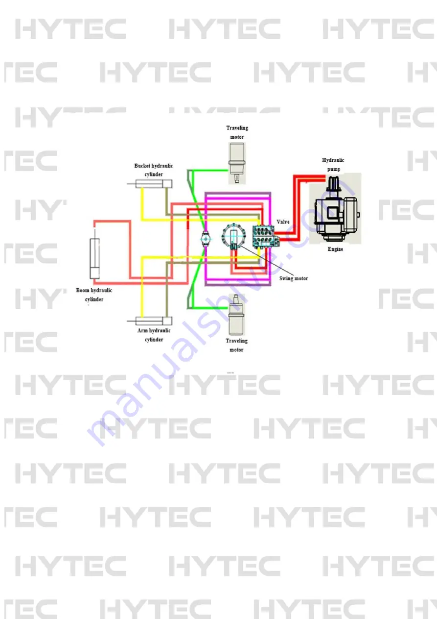
Section II Work principle of excavators
Diesel engine changes the chemical energy of diesel into mechanical energy that is then altered with hydraulic
gear pump to hydraulic energy that is distributed to each actuating element (such as hydraulic cylinder, swing
motor and traveling motor). After that, each actuating element transform the hydraulic energy back to mechanical
energy, driving the work equipment and running the complete machine.
Movement and power transmission route of excavator shown below:
1.
Traveling power route: diesel engine —— coupler —— hydraulic pump (mechanical energy changed to
hydraulic energy) —— distributor valve —— central swing joint —— traveling motor (hydraulic energy
changed to mechanical energy)—— sprocket —— rubber crawler—— starting of traveling
2.
Swing power route: diesel engine —— coupler —— hydraulic pump (mechanical energy changed to
hydraulic energy) —— distributor valve—— swing motor (hydraulic energy changed to mechanical energy)
—— slewing bearing —— realizing of wing
3.
Boom power route: diesel engine —— coupler —— hydraulic pump (mechanical energy changed to
hydraulic energy) —— distributor valve —— boom cylinder (hydraulic energy changed to mechanical
energy)——boom movement
4.
Arm power route: diesel engine —— coupler —— hydraulic pump (mechanical energy changed to hydraulic
energy) —— distributor valve —— arm cylinder (hydraulic energy changed to mechanical energy) —— arm
movement
5.
Bucket power route: diesel engine ——coupler —— hydraulic pump (mechanical energy changed to
hydraulic energy) —— distributor valve —— bucket cylinder (hydraulic energy changed to mechanical
energy) —— bucket movement
Central
slewing joint
Summary of Contents for F1000
Page 1: ...1 HYTEC F1000 EXCAVATOR OPERATION PARTS MANUAL ...
Page 4: ...4 Quick hitch Narrow bucket Log grab Mechanical thumb Auger Ripper Rake ...
Page 5: ...5 Section II Main performance parameters ...
Page 11: ...11 Hydraulic system structure of HYTEC F1000 Excavator I Rotary motor ...
Page 12: ...12 ...
Page 15: ...15 ...
Page 16: ...16 Section IV Schematics of main valve ...


