background image

Subject to change without notice.

Edition: 26 Feb. 2020      Ver. A0      Page 2/9

The motion detected by the master unit HIM38/RF passes to all other units programmed on the same group via RF transmission. The 
transmission can reach 30 meters indoor and 50 meters in open areas. A daylight sensor is also built-in to prevent the light switching 
on when surrounding natural light is sufficient.
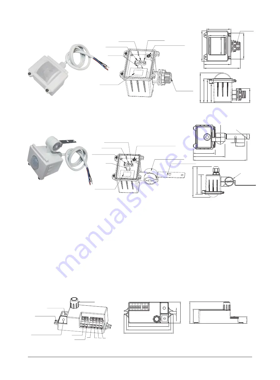
RF receiver

 serves as slave only, which turns on the light after receving the RF “ON” signal from the master. 

RF antenna

Rotary switch

Infrared remote receiver

1-10V+

1-10V

L’

N N L

Installation hole

-

71.5

4.2

37.5

38.3

25

11.8

78.2

87

1

HC034RF (1-10V output, RF grouping by rotary switch or remote control)

C. Attach to the shade by clamp 

B. Screw to the Luminaire by conduit 

Cable entry

Sensor module

PIR

LED indicator

Infrared receiver

Rotary switch for programing

Daylight sensor

59.6

66.6

89.9

0.825”

75

64

43.8

43

59.3

73.5

35.2

57.3 47.5

Sensor module

PIR

LED indicator

Infrared receiver

Rotary switch for RF grouping

Angle adjustment

Luminaire clamp 

Daylight sensor

163.2

33.7

28.5

4.5

15

96.8

66.6

4.5

93.8

84.5 59.3

29

Note: We recommend the mounting distance between sensor to sensor should be more than 4m to prevent sensors from     
          false-triggering.

Summary of Contents for HIM38/RF

Page 1: ...ve 1200W resistive max 20 devices max 40mA Capacitive Sensor RF Data Operation temperature Ta 20 O C 50 O C Environment IP65 IP rating Model No 0 2mW HF 5 8GHz 75MHz HF High Frequency microwave PIR Sensor principle Operation frequency Transmission power Detection range Detection angle RF frequency RF transmission distance Max O x H 18m x 15m 868MHz FSK mode default 30m indoor 50m outdoor 30s Warmi...

Page 2: ...ared remote receiver 1 10V 1 10V L N N L Installation hole 71 5 4 2 37 5 38 3 25 11 8 78 2 87 1 HC034RF 1 10V output RF grouping by rotary switch or remote control C Attach to the shade by clamp B Screw to the Luminaire by conduit Cable entry Sensor module PIR LED indicator Infrared receiver Rotary switch for programing Daylight sensor 59 6 66 6 89 9 0 825 75 64 43 8 43 59 3 73 5 35 2 57 3 47 5 Se...

Page 3: ...n is considered valid This is to prevent the sensor from false trigger by heat source air conditioner ventilation fans water pipe and elevators etc HF PIR either PIR or microwave mode to increase the detection capability and detection area 4 optional detection modes via remote control Sensor Sensor min 6m Distance Recommended between Sensors Pay attention The RF signal could be affected by big met...

Page 4: ...at the fixture never switches off but stays at preset dimming level even when natural light is sufficient zero cross point Alternating current Zero cross Relay Operation HIM38 RF Designed in the software sensor switches on off the load right at the zero cross point to ensure that the in rush current is minimised enabling the maximum lifetime of the relay 3 RF Grouping by Rotary Switch Maximum 15 c...

Page 5: ... Feb 2020 Ver A0 Page 5 9 Night Daytime HIM39 RF Brown LED driver L N DALI DALI L N Blue Red Black HIM38 RF Brown LED driver L N 1 10V 1 10V L N Blue Grey Red Black Wiring Diagram HC034RF LED Driver N N 1 10V N N L L L L _ 1 10V _ Wiring Diagram ...

Page 6: ...red for selection For single person walking across the detection range is reduced by 1 3 PIR detection H x D 15 x 18m max HF detection H x D 15 x 14m max PIR HF PIR tangential movement 18m HF walking across 14m 15m PIR detection L x W x H 18 x 5 x 15m max HF detection H x D 15 x 14m max PIR HF 15m 18m 14m 5m PIR HF PIR detection L x W x H 5 x 18 x 15m max HF detection H x D 15 x 14m max 15m 5m 14m...

Page 7: ...ight brightness during hold time Load Indication The light will flash ONCE rapidly after receiving the commamd from the remote control successfully Brightness Scene program 1 key commissioning Detection range for Transceiver only Press buttons in zone Detection range to set detection range at 100 75 50 10 Daylight threshold 1 Press button Start to program 2 Select the buttons in Detection range Da...

Page 8: ...e refer to steps below Short press Learn Erase button on RC to activate pairing mode and the receiver unit starts to beep once every second for 3min Note up to 30 units can be paired Short press Transmit button on RC the commander unit master unit beeps one time to send the transmission signal Upon receiving the transmission signal the receiver unit slave unit rapidly beeps 3 times in 1s to indica...

Page 9: ...Regarding precautions for PIR sensor installation and operation please kindly refer to www hytronik com download knowledge PIR Sensors Precautions for Product Installation and Operation 3 Regarding precautions for RF sensor installation and operation please kindly refer to www hytronik com download knowledge RF Sensors Precautions for Product Installation and Operation 4 Regarding Hytronik standar...

Reviews: