background image

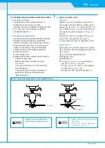
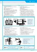
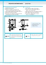
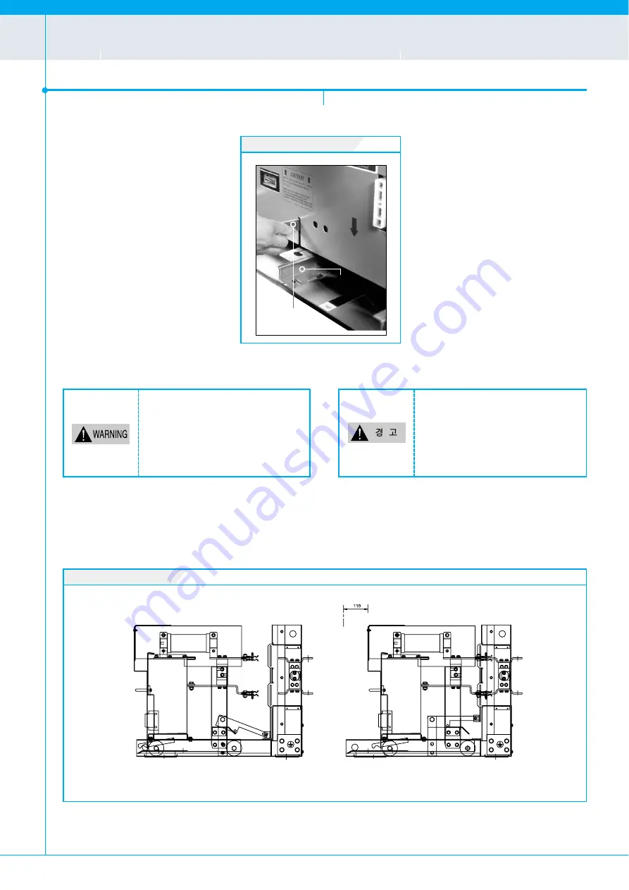
Fig. 3-5 / 그림 3-5

Fig. 3-4 / 그림 3-4

14

<<  

Vacuum Contactor Instruction Manual

Structure and Explanation of Operation

구조와 작동원리

03

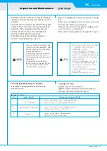
3.5 Inserting & Withdrawing 

1) How to insert the contactor in the E, F2 cradle

.

Inserting

Set the wheels of the contactor exactly   
on the guide rail of the cradle. 
At this time, more than two person 
have to lift up the breaker for full 
safety. If the contactor is pushed to the 
TEST position, the Interlock Pin 
prevents the draw-in at this position.   
Hold up the Interlock Lever (Fig. 3-4) 
and push the Contactor to the   
CONNECTION position. If the contactor 
is in the correct position, put the  
Interlock pin puts into the hole on the 
guide plate and the Female Contact   
will be inserted fully into the terminal.

Withdrawing

When a contactor is withdrawn, the contactor cannot 

be operated because of the interlock. 

In OPEN condition, hold up the Interlock Lever 

(Fig. 3-4) and pull out a contactor to the TEST position.

3.5 인출입 방법

1) E & F2 Cradle 인출입 방법

인입

레일위에 진공접촉기를 정확하게 올려놓아 주십시오.
이때 안전을 위해서 반드시 두명이상이 접촉기를
들어올리십시오. 
접촉기를 수평으로 밀어 넣으면 interlock lever에
연결된 인터록 봉이 interlock plate에 걸려 더이상
인입되지 않게 됩니다. 
이 때 interlock lever를 들어올리고 약간 밀어 넣어
interlock plate에 올려 놓고 힘껏 진공접촉기를 밀어
넣으면 시험 위치에서 접촉기가 lock됩니다. 
이 위치에서는 제어전원을 연결하여 필요시 내부
회로를 시험할 수 있습니다.
접속 위치로 삽입하기 위해서는 interlock lever를
다시 들어올리고 밀어 넣습니다.
인입이 완료되면 Isolating contact가 (그림 3-4)
terminal에 충분히 삽입되고 이때 interlock lever를
놓으면 interlock plate의 접속 위치 hole에
인터록 봉이 들어가면서 구속 됩니다.

인출

인출 도중에는 접촉기가 동작 할 수 없습니다.

Cradle으로부터 접촉기를 분리하고자 할 때는, 트립상태에서

interlock lever를 들고 접촉기를 당기면 됩니다.

Do not insert and withdraw the contactor 

in the closed condition.

Hold up the Interlock Lever during the 

inserting and withdrawing.

�인출입은 반듯이 접촉기를 open시킨후 행하여

주십시오.

심각한 사고 및 제품 손상의 위험이 있습니다.

�인출입시 interlock lever를 들어올리고 인출입

하십시오.

심각한 사고 및 제품 손상이 발생할 수 있습니다.

CONNECTION / 접속

TEST / 시험

Interlock Lever

Interlock Plate

Summary of Contents for HCA Series

Page 1: ... include all items regarding installation and maintenance procedures For more information please contact HYUNDAI Heavy Industries Co Ltd or one of our partners 당사 진공접촉기를 사용하시기 전에 반드시 본 취급설명서를 상세히 읽으신 후 설치 및 운전하십시오 본 취급설명서는 HCA 시리즈 진공접촉기에만 적용됩니다 본 취급설명서에는 설치 및 유지 보수에 관련된 모든 절차가 포함되어 있지는 않으므로 제품에 대해 더 많은 정보를 필요로 하시는 경우에는 당사로 연락하시기 바랍니다 기술적인 문의 및 A S사항은 가까운 지사 혹은 뒷 표지의 본사 설계 또는 A S 담당자에게 문의 바랍니다 HCA ...

Page 2: ...요한 내용을 기술하였습니다 제품을 부적절하게 설치하거나 유지 보수시에는 치명적인 인명 피해 및 재산 손실이 유발될 수 있으므로 포장해체 조립 작동 혹은 유지 보수를 하시기 전에 반드시 이 취급설명서를 충분히 읽고 이해하시기 바랍니다 설치 및 유지 보수는 유자격자나 전문 지식을 보유한 사람이 행하십시오 이 취급설명서는 HCA 시리즈 현대 고압 진공접촉기에만 적용되며 설치나 유지 보수에 관련된 절차가 모두 포함되어 있지 않으므로 제품에 대해 더 많은 정보를 필요로 하시는 경우에는 당사로 연락하시기 바랍니다 기호 설명 본 취급 설명서에서는 안전 주의사항을 위험 정도에 따라 위험 경고 주의 로 구분하고 있습니다 취급을 잘못 했을 경우 사망 또는 중상을 입을 절박한 위험 상태를 나타내 며 가장 위험한 상황입니다 피하...

Page 3: ...ement and check the tightness periodically It is important to replace the Vacuum Interrupter for the faculty of the contactor so should consult us to guarantee proper replacement Note and check the relationship between each wire and its associated auxiliary switch terminal 잘못된 유지 보수 작업은 심각한 사고 및 제품의 손상을 발생하거나 혹은 부하의 정상적인 작동을 방해할 수 있습니다 유지 보수 작업을 할 경우 반드시 앞단의 제어 회로 차단기를 open 시키고 컨트롤 플러그를 뽑아 진공접촉기의 ...

Page 4: ...ture of the Vacuum Interrupter 3 4 Structure of Cradle Type and Interlock 3 5 Inserting Withdrawing 3 6 Control Circuit Diagrams 4 Inspection and Maintenance 17 4 1 Visual Inspection 4 2 Periodic Inspection 4 3 Checking Vacuum and the Contact Erosion Limit 4 4 Replacements for Main Components 4 5 Troubleshooting 안전 조항 2 1 일반사항 5 1 1 사양 1 2 소비 전류 및 동작 시간 1 3 사용 조건 1 4 주문 체계 1 5 진공접촉기의 선정시 주의사항 1 6 ...

Page 5: ...상대 습도 85 이하 3 사용 고도 1000 m 이하 만약 본 고압 진공접촉기를 이상과 다른 조건에서 사용코져 할 경우에는 당사에 문의 바랍니다 진공접촉기 취급설명서 5 VC HCA Series General 일반사항 01 Rated Voltage 정격 전압 7 2 kV Rated Current 정격 전류 Power frequency withstand voltage 상용 주파 내전압 BIL 충격 내전압 Interrupting Rating 차단 용량 Category Operating Cycle 개폐 빈도 200 A 400 A 20 kV 60 kV 4 3 kA 50 MVA AC3 1200 operations 회 hour 시간 Control Voltage 제어전압 Continuously energized type...

Page 6: ...방식 Frame Structure 취부 방식 Control Source 제어 전압 Cradle Type Cradle 형태 Fuse Rating Fuse 사양 Accessories 부속품 3 3 kV 6 6 kV 200 A 400 A Continuously Energized 상시 여자 Latched 순시 여자 Fixed without Fuse Fuse 미부착 고정형 Fixed with Fuse Fuse 부착 고정형 Draw out without Fuse Fuse 미부착 인출형 Draw out with Fuse Fuse 부착 인출형 DC 110 V DC 220 V AC 110 V AC 220 V Class E Class F2 Class G Fuse Ratings 3 6 2 4 C L F A B D 1 2 3 4...

Page 7: ...V 6 6 kV 3 3 kV 3 3 kV 6 6 kV 6 6 kV 3 Transformer kVA 3 Condenser kVAR Load Fuse maker 6 3 10 16 20 25 30 31 5 40 50 63 80 100 125 160 200 250 315 355 2 125 2 160 2 200 2 250 SIBA 90 100 125 160 200 275 315 400 500 600 500 650 750 LG 37 75 90 200 220 400 450 630 710 800 LG 75 160 185 400 450 800 900 1250 1500 SIBA 50 80 100 125 160 200 250 315 400 500 630 750 900 800 1000 1250 LG 10 20 30 50 75 1...

Page 8: ...perty 2 3 Storage If contactors must be stored for a period prior to use they should be stored only in dry dust free and well ventilated rooms with contactors in the open condition HCA 시리즈 현대 고압 진공접촉기는 공장에서 제조된 후 포장되기전 시험 및 검사를 시행하였습니다 이 제품은 운송 및 보관 중에 파손되지 않도록 포장되어 운반됩니다 2 1 인수 진공접촉기를 처음 인수할 때는 운반도중 제품의 파손 손상 및 결여된 부품 등이 있는지 검사하여 주십시오 어떤 하자를 발견하였을 시 즉시 가까운 영업이나 지사로 연락하시기 바랍니다 제품 인수후 다음 사항을 점검하십시오...

Page 9: ...ors electrically in the test position and confirm that the ON OFF indicator works properly 3 Confirm that no tools and materials are left near the contactor 2 4 설치 작업 1 진공접촉기를 배전반에 설치하기 전 접촉기의 Type 정격 및 손상여부 를 재확인하고 마른걸레로 먼지 및 더러운 부분을 닦아냅니다 2 수평편차가 1 mm 이내가 되도록 설치되어야 하며 설치 관련 치수는 HCA Vacuum Contactor Catalogue를 참조바랍니다 3 연결 부위를 깨끗이 닦아낸후 연결 및 접지 작업을 하여 작업시 제품 에 무리한 힘이 걸리지 않도록 주의하십시오 2 5 운전 전 점검사항 1 ...

Page 10: ...hing the latch device holds the Moving core of the contactor closed against the closing coil after the contactor is energized closed and the control source is removed 3 1 구조 Fig 3 1은 HCA 시리즈 현대 고압 진공접촉기의 내부구조를 보여줍니다 3 2 동작 원리 1 투입 동작 투입용 코일 이 자화되면 전면 구동판 을 당기게 되고 동시에 트립용 스프링 이 압축됩니다 또한 구동축 을 중심으로 하여 상부 구동판 이 압축용 스프링 과 진공밸브 의 가동부를 밀어 올려 투입 상태가 됩니다 순시여자식 기계적 latching 접촉기에서는 제품 하단에 설치된 latch 기구가 투입 완...

Page 11: ...전원을 인가하면 전면 구동판 을 고정하고 있던 latch 기구가 해제되고 동시에 압축 되었던 트립 용 스프링 이 회복되어 개로 상태가 됩니다 정전시에도 트립 버튼이나 별도로 설치되어 있는 콘덴서 트립기구 CTD 에 의해 트립이 가능합니다 3 3 진공밸브 구조 The Vacuum Interrupter has the Contact Stem the Contacts the Bellows and the Ceramic Insulator The contact is designed to guarantee 1 million operations and to restrain the transient recovery voltage under 1 A chopping current The low pressure in the Vacu...

Page 12: ...rlock makes the contactor operate only in the test and service position and prevents the contactor from closing mechanically between TEST and CONNECTION position Manual Closing Hole Only latched types have a Manual Closing Hole which is used to close the contactor manually 3 4 인출형 구조 및 구속장치 1 인출형 구조 인출형은 Fig 3 3과 같이 구성되어 있습니다 개폐 지시기 ON은 투입 OFF는 트립 상태를 나타냅니다 계수기 ON OFF 개폐횟수를 표시합니다 제품 생산 후 성능 시험에 의하...

Page 13: ...비고 1 2 If the contactor is closed it cannot insert and withdraw contactor in the TEST or CONNECTION position 투입상태에서 진공접촉기는 접속위치로 인입이 안됨 The contactor cannot be closed during the process of inserting and withdrawing 인출입 도중에는 진공접촉기가 투입되지 않음 Move the contactor to TEST or CONNECTION position and then close the contactor 진공접촉기를 OFF한 후 시험 및 접속위치로 이동시킨 후 투입 The Interlock Pin attached in frame inside prev...

Page 14: ...e interlock In OPEN condition hold up the Interlock Lever Fig 3 4 and pull out a contactor to the TEST position 3 5 인출입 방법 1 E F2 Cradle 인출입 방법 인입 레일위에 진공접촉기를 정확하게 올려놓아 주십시오 이때 안전을 위해서 반드시 두명이상이 접촉기를 들어올리십시오 접촉기를 수평으로 밀어 넣으면 interlock lever에 연결된 인터록 봉이 interlock plate에 걸려 더이상 인입되지 않게 됩니다 이 때 interlock lever를 들어올리고 약간 밀어 넣어 interlock plate에 올려 놓고 힘껏 진공접촉기를 밀어 넣으면 시험 위치에서 접촉기가 lock됩니다 이 위치에서는 제어전원을 ...

Page 15: ...ition the Stopper is pushed out to prevent the unexpected moving of the Fixing Screw M Cradle 인출입 방법 Screw 구동방식으로서 시험 접속 각 위치에서는 interlock이 자동으로 이루어집니다 준비 레일위에 차단기를 정확하게 올려놓아 주십시오 이때 안전을 위해서 반드시 두 명 이상이 진공접촉기를 들어올리십시오 Manual lock 상태가 unlock 위치에 있는지 확인하십시오 시험 위치로 이동 진공접촉기가 cradle의 멈춤용 볼트에 부딪혀 삽입이 안될 때까지 밀어 넣으십시오 Manual lock handle을 양옆으로 밀어내어 lock 상태를 만드십시오 인입 진공접촉기는 시험 접속 위치에서 자동으로 구속 작동이 이루어집니다 Ra...

Page 16: ...Operation 구조와 작동원리 03 3 6 Control Circuit Diagrams 3 6 제어 회로도 VZ Closing Switch R Resistor CC Closing Coil Z TNR X Relay TC Trip Coil CTD Condensor Trip Device Aux SW Auxiliary Switch FOR FIXED TYPE FOR DRAWOUT TYPE CONTROL PLUG FOR FIXED TYPE FOR DRAWOUT TYPE CONTROL PLUG CONTROL PLUG CONTROL PLUG CONTROL PLUG FUSE MELTING INDICATOR TEST CONNECTION POSITION SWITCH PT 2SETS PT 1SET ...

Page 17: ...연락하여 점검 조치를 받으시기 바랍니다 No Items 점검사항 Procedure of Checking 점검 방법 1 2 3 ON OFF Indicator Abnormal smell 소음이나 냄새 Damage 손상 Check if each state of ON OFF is identified accurately 투입시 ON 트립시 OFF의 표시가 정확한지 확인 합니다 Check if the Closing Coil is overheated or burned 비정상적인 소음이나 냄새가 나는지 확인 합니다 Check the crack break and discoloration 균열 파손이나 변색이 있는지 확인 합니다 Failure to maintain the equipment could result in seri...

Page 18: ...e time Check if the fuse melting indicator operates smoothly If not put the grease on the moving parts Check and tighten bolts Check if the contact erosion is expired If it is expired each VI of 3 phases should be replaced at the same time Check vacuum by using the Vacuum Tester Check and tighten bolts Check for scratches or rust If the coil discolored replace it Check and tighten bolts One should...

Page 19: ...upters this distance is about 1 0 2 0 mm If it is reduced to 0 5mm the three interrupters must be replaced Checking the contact erosion is important to evaluate the efficiency of the interrupters Refer to the Fig 4 1 4 3 진공밸브의 진공상태와 마모 확인 1 진공상태 점검 진공접촉기는 진공의 우수한 절연내력에 의해 성능이 유지되고 있으므로 진공도의 유지가 매우 중요합니다 진공밸브의 진공도가 pachen의 절연 내력 임계치 1 10 3 mbar 이하로 떨어지는 경우 차단 및 개폐능력이 저하될 수 있으므로 정기점검시 혹은 매 3년 주기로 진공...

Page 20: ... mm backward Insert new fuses and tighten the bolts Reverse the action in the previous step 4 4 주요 부품 교체 교체 작업을 행하기 위해서는 우선 진공접촉기를 인출하여 enclosure 밖으로 빼냅니다 고정형일 경우에는 주모선과 ground선을 풀어냅니다 그리고 제품 전면 cover 및 절연 보호판을 풀어냅니다 이때 아크릴제의 절연 보호판이 손상되지 않도록 주의하여 주십시오 1 퓨즈 교체 퓨즈 상간 절연 베리어를 제거합니다 퓨즈 홀더 의 전단 및 후단 2개소의 상부 볼트 M8 를 풀어냅니다 퓨즈 용단 검출기가 있는 경우에는 퓨즈 용단 검출기의 supportor를 풀어내고 퓨즈 용단 검출기가 없는 경우에는 하부 볼트 M6 을 풀어냅니다...

Page 21: ...접촉기 취급설명서 21 VC HCA Series 3 보조 스위치 교체 보조 접점 구동판 을 풀어냅니다 보조 스위치 지지대 의 고정 볼트 를 풀어냅니다 제어용 스위치 를 교체할 경우에는 볼트 와 연결 cable을 풀어낸 후 교체합니다 보조 스위치 가 불량일 경우에는 볼트 M4 와 연결 cable을 풀어낸 후 불량 스위치를 교체합니다 위의 순서를 역순으로 재조립 후 수동 투입핸들 을 이용하여 수동으로 시험하여 이상 유무를 확인합니다 전기적으로 시험하여 이상 유무를 확인합니다 3 Replacing the Auxiliary Switch Release the pusher Release the support and remove the wires from the auxiliary switch If the closing ...

Page 22: ... separate the flexible connector Loosen the upper fixing bolts from the upper connector Replace the new vacuum interrupter Reverse the action in the previous step and check the stroke and wipe of the vacuum interrupter 22 Vacuum Contactor Instruction Manual Inspection and Maintenance 검사와 유지보수 04 Vacuum Interrupter 진공밸브 Insulation Rod 절연로드 Upper Connector Flexible Connector It is important to repla...

Page 23: ...ary adjust the height of a roller by releasing the bolt Roller의 높이를 확인하고 나사를 풀어 roller의 높이를 조절함 Loose bolts 나사가 풀림 Defective operation of the Control Switch 리미트 스위치의 오동작 Blown fuse 퓨즈가 용단됨 Defective resistor Resistor 불량 Interrupter without vacuum 진공밸브의 진공 파손 Punctured rectifier 정류기가 파손됨 The control plug is not connected 컨트롤 플러그가 연결되지 않음 Check the tightness of bolts 나사가 제대로 조여졌는지 점검함 Check the wiri...

Page 24: ... 1 847 228 8845 Fax 1 847 437 3574 London 2nd Floor The Triangle 5 17 Hammersmith Grove London W6 0LG UK Tel 44 20 8741 0501 Fax 44 20 8741 5620 Tokyo 8th Fl Yurakucho Denki Bldg 1 7 1 Yuraku cho Chiyoda gu Tokyo 100 0006 Japan Tel 81 3 3212 2076 3215 7159 Fax 81 3 3211 2093 Osaka I Room 5th Fl Nagahori Plaza Bldg 2 4 8 Minami Senba Chuo Ku Osaka 542 0081 Japan Tel 81 6 6261 5766 5767 Fax 81 6 626...

Reviews: