
HYUNDAI Video Door Phone
| HA-201 / HAC-201
10|11
INSTALLATION
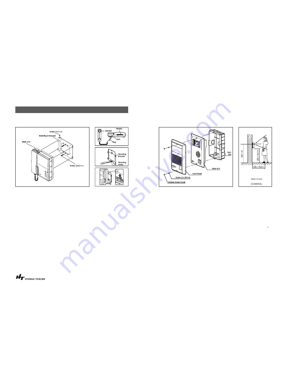
Installation
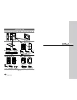
1. After determining the mounting locations for both the outside camera and
inside monitor, it is recommended to mount the camera and monitor to the
height of an average adult’s eye level from the ground (Approx. 1500mm / 59
inches).
2. At the selected monitors mounting location, attach the mounting bracket firmly
to the wall.
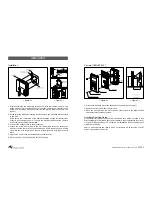
Drill a hole in the center area of the bracket just large enough for the electrical
wiring to pull through the hole. Connect the electrical wires from the camera
unit to the monitor-wiring terminal strip.
3. Connect the handset cord to the monitor unit.
4. Attach the wired monitor unit to the wall mounting bracket by setting the
monitor over the four bracket hook and slide it down, Insert the tiny machine
screw into the hole in the tab at the top of the bracket to hold the monitor in
place.
5. Plug the AC power cord into a standard household outlet.
6. Place the Power “On/Off” switch in the “On” position.
< Figure 2 >
< Figure 3 >
INSTALLATION
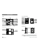
Camera (HCB/HCC-300)
1. It is recommended to mount the flush box of the camera into the wall.
2. Remove the front panel from the main unit
3. Place the front panel on the main unit and attach them to the flush box with
two tamper proof screws provided.
Important Mounting Notes:
Do not install the monitor and camera units where they will be exposed to dirt,
direct sunlight (or other strong light), direct moisture, high temperature (over 40 C)
or high humidity conditions. Do not select an installation location subjected to
vibration or pounding.
Select a mounting location close to an AC outlet where it is easy to view the CRT
screen and operate the monitor.
< Figure 4 >
< Figure 5 >
Summary of Contents for HA-201
Page 12: ...Memo ...


