background image

Installation/Connection

4

Installation

General notes

•   Choose the mounting location 

where the unit will not interfere with 
the normal driving function of the 
driver.

•   Before finally installing the unit, 

connect the wiring and make sure that 
the unit works properly.

•   Consult with your nearest dealer 

if installation requires the drilling of 
holes or other modifications of the 
vehicle.

•   Install the unit where it does not 

get in the driver’s way and cannot 
injure the passenger if there is a 
sudden stop, like an emergency stop.

•   Avoid installing the unit where it 

would be subject to high temperature, 
such as from direct sunlight, or from 
hot air, from the heater, or where 
it would be subject to dust, dirt or 
excessive vibration.

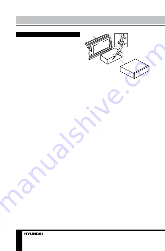
DIN front-mount (Method A)

1.  Install the sleeve into the 

dashboard; ensure it is installed with 
the correct side and there are no 
obstacles (wires, dashboard elements, 
etc) for the unit installation.

2.  After installing the sleeve into the 

dashboard, bend tabs fitting to the 
size of the dashboard to fix the sleeve 
in place.

3.  Make the necessary wire 

connections. Ensure the connections 
are correct.

4.  Install the unit into the sleeve until 

the side locks are fixed.

2

1

182

53

1. Dashboard
2. Sleeve tab to bend

Trim frame installation

To install the trim frame, press it 

to the unit body and push it to fix it 
in place. This should be done before 
installing the front panel; otherwise you 
are not able to install the trim frame.

DIN rear-mount (Method B)

For this method, use the screw 

holes in the lateral sides of the unit. 
Fix the unit with the help of the factory 
radio mounting brackets.

1. Select a position in which the 

screw holes of the brackets (3) are 
aligned with the screw holes in the unit 
body, and screw in two screws (2) in 
each side.

2. Screw.
3. Factory radio mounting brackets.
4. Vehicle dashboard.
5. Lock (remove this part).

Summary of Contents for H-CCR8100

Page 1: ...USB SD MMC USB SD MMC MEDIA PLAYER Instruction manual H CCR8100...

Page 2: ...nnector Operation Control elements Front panel Inner panel Remote controller Changing the battery LCD layout General operations Turning on off Mode selection Volume control Mute function Loudness Audi...

Page 3: ...an outage Disconnect the vehicle s negative battery terminal while mounting and connecting the unit When replacing the fuse be sure to use one with an identical amperage rating Using a fuse with a hig...

Page 4: ...correct side and there are no obstacles wires dashboard elements etc for the unit installation 2 After installing the sleeve into the dashboard bend tabs fitting to the size of the dashboard to fix t...

Page 5: ...the unit Then insert the left fastening on the panel into the fixing hole on the left part of the unit Press on the upper right part of the panel until a click Ensure that the panel is properly fixed...

Page 6: ...the ISO connector then connect the ISO connectors as illustrated 2 For connections without the ISO connectors check the wiring in the vehicle carefully before connecting incorrect connection may caus...

Page 7: ...3 Front right Grey 4 Battery 12V Yellow Front right Grey White 5 Power antenna Orange Front left Green 6 Front left Green White 7 Ignition Red Rear left Brown 8 Ground Black Rear left Brown White Pow...

Page 8: ...PEN button 8 BND PTY button 9 4 RDM button 1 2 3 4 5 6 8 9 10 11 12 13 14 15 16 17 18 7 10 5 button 11 6 button 12 IR port 13 MOD TA button 14 button 15 button 16 F PS button 17 AUX in jack 18 USB por...

Page 9: ...ing up Insert the battery tray into the remote control Store the battery where children cannot reach If a child accidentally swallows the battery consult a doctor immediately Do not recharge short dis...

Page 10: ...eneral operations Turning the unit on off Press PWR button on the panel or button on the RC to turn the unit on Press and hold the button again to turn the unit off Mode selection Press MOD TA button...

Page 11: ...ton on the RC repeatedly until BEEP ON OFF is displayed Rotate VOLUME knob or press VOL VOL buttons on the RC to select between ON beep sound is heard when a button is pressed and OFF no sound is hear...

Page 12: ...press VOL VOL buttons on the RC to switch between stereo reception or mono reception Improvement of reception of distant stations can be done by selecting mono mode which may cut down some reception n...

Page 13: ...olk Travel Leisure Document When PTY is selected the radio starts to search corresponding PTY information and stops if the corresponding PTY information is detected If no buttons are pressed within se...

Page 14: ...defective USB drives may cause mechanical or thermal changes of elements of the unit as well as failure of internal elements of USB port Such damages are not warrantee cases Usage of external USB driv...

Page 15: ...ntinuously repeat the current track Press again to cancel Random Press 4 RDM button to play all the tracks in the current folder in random order Press again to cancel ID3 tags If an MP3 file contains...

Page 16: ...um Adjust volume to a desired level Wiring is not properly connected Check wiring connection The radio does not work The antenna cable is not connected Insert the antenna cable properly The radio stat...

Page 17: ...ions Weight 178 50 78 mm 0 6 kg Temperature range 200 C 600 C FM Stereo Radio Frequency range 87 5 108 0 MHz Presettable stations 18 Stereo separation 35 dB 1 kHz MW AM Radio Presettable stations 12 F...

Page 18: ...19 19 20 20 20 20 21 21 21 22 23 23 23 25 25 25 25 26 26 27 27 27 27 28 28 28 28 28 28 28 29 29 29 29 29 29 30 30 30 30 31 32 32 32 32 33 33 33 33 33 33 33 34 34 34 35 35 beep AUX RDS AF TA PTY USB S...

Page 19: ...19 20...

Page 20: ...20 1 2 3 4...

Page 21: ...21 2 1 182 53 1 2 1 3 2 2 3 4 5 2 2 5 5 4 3 1 2...

Page 22: ...22 3 OPEN...

Page 23: ...23 4 5 A ISO 1 ISO 2 ISO...

Page 24: ...24 A B 1 2 3 4 12 5 6 7 8...

Page 25: ...T 2 VOLUME knob SELECT 3 1 4 2 INT 5 3 RPT 6 Display 7 OPEN 8 BND PTY 9 4 RDM 1 2 3 4 5 6 8 9 10 11 12 13 14 15 16 17 18 7 10 5 11 6 12 IR port 13 MOD TA 14 15 16 F PS 17 AUX 18 USB 1 2 3 1 SD MMC 2 3...

Page 26: ...26 1 2 3 4 5 6 7 8 9 10 11 12 13 14 15 1 2 MUTE 3 4 BND 5 VOL 6 TA 7 AF 8 9 MODE 10 VOL 11 CLK 12 13 SEL 14 APS 15 PTY 1 2 CR 2025 3...

Page 27: ...27 PWR MUT MOD MODE AUX USB USB 00 42 VOLUME VOL VOL 1 2 3 4 5 6 7 8 9 10 11 12 13 14 15 16 17 1 2 3 4 5 6 7 8 9 10 11 12 13 EON 14 AF 15 TA 16 TP 17 PTY...

Page 28: ...CT SEL VOL BAS bass TRE treble BAL balance FAD fader VOLUME VOL VOL Bass Treble 10 10 Balance L10 R10 Fader R10 F10 SELECT SEL EQ OFF VOLUME VOL VOL FLAT CLASS ROCK POP Beep SELECT SEL BEEP ON OFF VOL...

Page 29: ...29 MP3 BND PTY BND FM1 FM2 FM3 AM1 AM2 6 MANUAL F PS APS 6 6 F PS APS FM SELECT STEREO MONO VOLUME STEREO MONO RDS RDS RDS AF...

Page 30: ...30 SEL AF AF RDS RDS AF AF AF RDS RDS AF AF TA MOD TA TA TA PTY FM RDS BND PTY PTY 1 6 BND PTY PTY 1 6 1...

Page 31: ...31 2 3 4 5 6 PTY SELECT SEL VOLUME VOL VOL TA SEEK TA ALARM TA SEEK TA TA ALARM PI SOUND MUTE PI sound PI PI PI mute MASK DPI MASK ALL AF...

Page 32: ...32 MASK DPI MASK DPI MASK ALL RDS RETUNE L RETUNE S RETUNE S L SHORT LONG RETUNE S L Retune TA TA SEEK USB SD MMC USB USB USB SD MMC USB SD MMC 16 USB USB 1 1 2 0 USB 500 USB USB USB USB BIN USB USB S...

Page 33: ...33 F PS APS VOLUME VOL VOL SELECT SEL 5 6 1 2 INT 10 3 RPT 4 RDM ID3 MP3 ID3 ID3...

Page 34: ...34...

Page 35: ...35 1 1 2 1 3 ISO 1 4 1 1 2010 2019 R31982101 01792 2011 1 5X20 1 2 2 5 1 6 1 7 1 4 x 45 4 8 5 USB SD MMC 16 178 50 78 0 6 200 600 FM 18 87 5 108 0 35 1 AM 12 522 1620 30 RCA 2 H CCR8100_IM_01...

Reviews: