PAGE 15
Rev 2
5.8
Tandem compressors with timed control unit. (fig. 17).
5.8.1
.1 Fit the plug in the power socket (fig. 13) and turn the pressure switch to position
“I” (ON). Turn the master power switch “A” on the control unit to position I – power On is
signalled by white indicator-light “E” going on.
5.8.2
.2 Turn switch “B” to start the compressor.
5.8.2.1
.1 Pos. 1 pumping element n. 1 only is operating
5.8.2.2
.2 Pos. 2 pumping element n. 2 only is operating
5.8.2.3
.3 Pos. 3 both pumping elements are operating simultaneously,
at staggered starting times.
5.8.3
.3 The compressor is fully automatic, and is controlled by the pressure switch
which stops it when tank pressure reaches maximum value and restarts it when it falls
to minimum value.
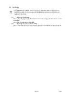
The head/cylinder/delivery tube unit can reach high temperatures. Take care when working near
these parts, and do not touch them to avoid possible burns (fig. 18 - 19).
IMPORTANT
The electro-compressors must be connected to a power socket protected by a suitable differential
switch (thermal-breaker). The motor of GM-TR compressors is equipped with an automatic
thermal breaker located inside the winding – this stops the compressor when motor temperature
reaches excessively high values.
If the breaker is tripped, the compressors restarts automatically after 10 to 15 minutes. The
motors of compressor models VX are supplied with a manually resetting automatic amperometric
thermal-breaker, located outside the terminal board cover.
When the breaker is tripped, wait for a few minutes and then reset the breaker manually (fig. 20).
The motors of the AB series compressors are supplied with a manually resetting amperometric
thermal-breaker, located on the terminal board cover. When the breaker is tripped, wait for a few
minutes and then reset the breaker manually (fig. 20).
The safety device is automatic in three-phase and silent compressors. When the thermal-breaker is
tripped, the pressure switch is released to “0” (OFF) position.
Wait for a few minutes and return the pressure switch to “I” (ON) position (with the exception of
models: AB 100/245-335 Three-phase - AB 150/ 245-335 Three-phase - AB 200/245-335 Three-
phase). For compressors supplied with a control unit, the thermal-breaker is installed inside the
control unit. When the thermal-breaker is tripped, observe the following procedure (fig. 22):
•
Turn the switches on the control unit cover to position “0”, open the cover and press push-
button 1 of the thermal-breaker. Close the cover of the control unit and restart the compressor,
observing the operations described in the paragraph “Starting compressors with control unit”.
The same instructions apply to compressors powered at 60 Hz.
5.9
Adjusting the operating pressure (fig. 23).
5.9.1
.1 You do not have to use the maximum operating pressure at all times. On the
contrary, the pneumatic tool being used often requires less pressure. On compressors
supplied with a pressure reducer, operating pressure must be correctly adjusted.
5.9.2
.2 Release the pressure reducer knob by pulling it up, adjust pressure to the
required value by turning the knob clockwise to increase pressure and anti-clockwise to
reduce it.
5.9.3
.3 When you have obtained optimum pressure, lock the knob by pressing it
downward (fig. 23). For pressure reducers equipped without a pressure gauge, the set
pressure can be seen on the graduated scale located on the reducer body.
Summary of Contents for HY30100
Page 1: ...ELECTRIC AIR COMPRESSOR Models HY3050 HY30100 HY3150 User Manual...
Page 5: ...2 UNPACKING USAGE INSTRUCTION PAGE 5 Rev 2...
Page 6: ...PAGE 6 Rev 2...
Page 7: ...P AGE7 Rev 2...
Page 23: ...PAGE 23 Rev 2...


