background image

New R-Line Refuse Collection Micro 
User Manual RCM10  
 

35 

4.4 

Collection tank emptying


Preliminary remarks 

In these phases, the operator will be: 

Inside the driving cab, for the collection tank emptying phase; 

Outside the cab for the rear door closing phase. 


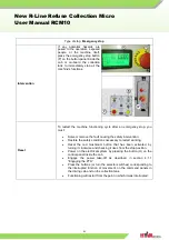
Step


Action


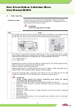
  After  having  made  sure  that  no  obstacles  or  people  are  in  the  vehicle's  vicinity,  the 

operator must approach the point at which the bin is to be unloaded. 

  Perform  the  operations  described  in  paragraph  4.1.1  "Engaging  the  PTO",  as  far  as  step 

(2), then proceed as follows. 


ATTENTION


Check the parking brake is activated.


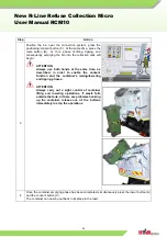
Activate the parking brake. 


Press the button (A), the hatch opening 


With  exclusive  reference  to  RCM10  equipment, 
once  the  collection  tank  has  been  emptied,  in 
order  to  prevent  any  residual  waste  material  from 
remaining  inside  it,  the  expulsion  plate  can  be 
shaken  five  times  by  pressing the button (B),  thus 
causing  any  stuck  waste materials to fall off. 


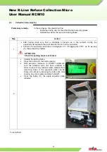
Press  the  button  (C),  the  waste  expulsion  plate 
retracted 


To be defined... 

Summary of Contents for R Series

Page 1: ...NEW R LINE REFUSE COLLECTION MICRO LOADING TRANSPORT UNLOADING RCM10 RCM10 ...

Page 2: ...ata 17 3 4 2 Characteristics of the treated product 17 3 4 3 Characteristics of the sound emissions noise 17 3 5 FUNCTIONING PRINCIPLE 18 3 6 INTENDED USE AND UNINTENDED USE 20 3 7 WORK AREA S COMMAND AREA S AND DANGEROUS AREA S 21 3 7 1 Work areas and dangerous areas 22 3 8 SAFETY DEVICES 23 3 9 PERSONAL PROTECTIVE EQUIPMENT 24 3 10 INDICATOR PLATES ON THE MACHINE 25 3 11 DESCRIPTION OF THE COMMA...

Page 3: ...vement zone 53 4 12 2 Checking topping up the hydraulic oil level 54 4 12 3 Greasing the hinging and sliding points 55 4 12 4 Changing the hydraulic oil 56 4 12 5 Replacing the unloading filter 57 4 12 6 Storing the machine 58 4 13 SCRAPPING AND DISPOSAL 59 4 13 1 Disposing of electric and electronic equipment 60 4 14 PROBLEMS AND SOLUTIONS PRELIMINARY OPERATIONS 61 4 14 1 Troubleshooting 63 4 14 ...

Page 4: ...stem failure cannot be resolved using the methods provided in this Manual please contact the distributor or the manufacturer directly Our wide service network will always be available to help you remove the malfunction To guarantee the safety of the operators and avoid any damage to the system it is essential to study the instruction manual thoroughly before carrying out any operation on the machi...

Page 5: ...ng has been removed 2 3 Control panel There is an emergency stop button on the control panel In case of emergency press this button to stop all the moving parts immediately only superstructure A release button is provided on the master control panel In case of emergency press this button to retract the garbage compaction mechanism back to its initial position When this button is released the garba...

Page 6: ... press the emergency button and then press the release button Please follow this rule otherwise personal injury or even death may occur to the operator Before carrying out any maintenance work on the RCM10 cut off the PTO ENGINE supply first In order to avoid any person from switching on the power supply accidentally please turn off the key of the engine 2 7 Filling garbage into the RCM10 Elastic ...

Page 7: ...o pass or stand in the working range of the machine Residual risk of crushed hands and feet DO NOT CLIMB Warning Consult the instruction use and maintenance manual It is prohibited to use high pressure spraying for cleaning the control panel Unauthorised personnel are forbidden from carrying out any maintenance operations System code identification plate inside the electric panel The insertion of ...

Page 8: ...d unloading of the materials treated during the work Simple adjustment start up or reset operations following any forced interruption Requisites for specialised mechanical maintenance technicians Qualified technician able to drive the vehicle in normal conditions operate it with the protection devices deactivated and intervene on the mechanical and hydraulic elements to perform all necessary adjus...

Page 9: ...New R Line Refuse Collection Micro User Manual RCM10 9 ...

Page 10: ...ed by the machine Minimum capacity 120 litres Maximum capacity 1100 litres Characteristics of the bins that can be lifted by the machine The machine can unload any type of bins with a capacity ranging from 120 to 1100 litres with the following types of connections CE plate in Model field VD DIN arm connectors for 660 to 1100 litre flat lid bins VE Europa arm connectors for 1100 litre bins RV Verti...

Page 11: ...al RCM10 11 3 2 Machine composition Main units The main units that make up the machine are 1 Vehicle frame 2 Subframe 3 Container 4 Rear door referred to as the Hatch 5 Waste expulsion bulkhead referred to as the Plate 6 Compacting shovel Fig 2 1 ...

Page 12: ...rame can be of any make and model as long as it is approved with the laws in force in the country where it is marketed 3 3 2 Subframe Preliminary remarks A subframe which can be removed if necessary is installed between the vehicle s frame and the container bin and is fastened to the frame in a secure yet flexible manner in order to allow the vehicle s frame to bend freely Characteristics The subf...

Page 13: ...ontainer made with framework which has a profiled rear section in order to give the entire unit a pleasing aesthetic appeal Characteristics The container is made from sheet plates with reinforcement ribs at the side Some sheet metals are of high tensile wearable steel and corrosion resistance material Fig 2 3 Fig 2 4 ...

Page 14: ...s opened by two hydraulic jacks during the unloading phase Both hydraulic jacks are equipped with stop valves to prevent the hatch from closing in the event that the hydraulic hoses are broken In order to ensure the proper containment of any liquid waste the structure has been equipped with a gasket that makes contact with a specific edge on the hatch itself The hatch can be locked using two cylin...

Page 15: ...sists of a rigid inclined structure that moves on plastic slides with an extremely low friction coefficient on a central guide Fig 2 6 Characteristics This bulkhead is moved by a telescoping hydraulic jack Thanks to a dedicated hydraulic system the bulkhead automatically retracts during the compacting phase in order to allow the waste material to be compacted as much as possible Fig 2 6 ...

Page 16: ... support carriage that moves within the dedicated guides which in turn is attached to a rotating vane that allows for the waste material at the top of the container to be compacted The compacting operations are carried out hydraulically and when the container is full a system of hydraulic valves prevents the shovel from over compacting the waste materials thus safeguarding the integrity of all the...

Page 17: ...ss municipal solid waste MSW Products not allowed ATTENTION All the products not listed in the machine use section and in paragraph 2 4 2 Characteristics of the treated product should be considered not allowed improper and therefore forbidden HYVA MECHANICS CHINA CO LTD declines all liability for injury to persons or damage to property resulting from the failure to observe this warning 3 4 3 Chara...

Page 18: ...to the container pick up area The operator stops the vehicle keeping the engine switched on then uses the commands in the cab figure A or B based on the version supplied to engage the power take off via the couplings of the gearbox to activate the hydraulic circuit The operator engages the parking brake exits the cab and goes to the container pick up area The operator prepares the hook up system b...

Page 19: ...n order to do this use the buttons and selectors on the control panel which is located either inside or outside the cab based on the version supplied This operation is performed by using the appropriate button 7 to move the waste expulsion plate Once it has arrived at the end of its stroke the plate can be shaken to eliminate any residues that have not yet been expelled using the shaker activation...

Page 20: ... manual is considered IMPROPER USE and Hyva declines all liability for any damage caused to persons animals property or to the machine itself ATTENTION Any use other than that for which the machine was designed may cause dangerous conditions for the operators maintenance technicians any other persons exposed and the machine itself Operators The manufacturer specifies the presence of only one opera...

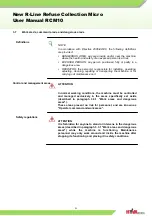
Page 21: ...rting the machine or for carrying out maintenance on it Control and management areas ATTENTION In normal working conditions the machine must be controlled and managed exclusively in the areas specifically set aside described in paragraph 3 3 1 Work areas and dangerous areas These areas present no risk for personnel and are known as Operator command and work areas Safety regulations ATTENTION It is...

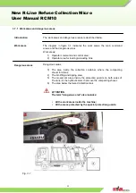
Page 22: ...a 2 Operator area for loading unloading bins Dangerous areas Dangerous areas 3 The area inside the collection container where the compacting shovel functions 4 The bin lifting and tipping area 5 The movement area inside the protection guards on both sides of The tank of the hydraulic arms that move the compacting shovel 6 The area below the raised collection tank ATTENTION The term dangerous area ...

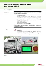
Page 23: ...ulic cylinders for lifting the hatch fitted with double acting stop valves that block the cylinders in the position they are in when the hydraulic pressure fails 4 Fixed protection devices 5 Hatch closure safety latches 6 Rear edge closure control micro switch The diagram in figure 3 3 shows the positioning of the safety devices installed on the machine Safety regulations ATTENTION It is absolutel...

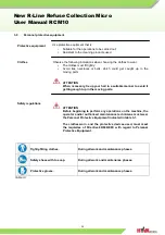
Page 24: ...y tie up your hair in a suitable manner to avoid it getting caught up in the moving parts Safety regulations ATTENTION Before beginning to perform any operations on the machine the operator and or authorised maintenance technicians must wear the Personal Protective Equipment indicated in table 3 1 The clothes worn and the protective devices used must meet the requisites of Directive 89 686 EEC wit...

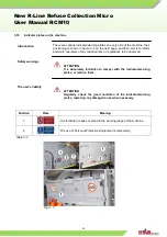
Page 25: ...ators of any residual risks or regulations to be observed Safety warnings ATTENTION It is absolutely forbidden to tamper with the indicator warning plates or remove them The user s liability ATTENTION Regularly check the good condition of the indicator warning plates replacing any damaged ones when necessary Position Plate Meaning 1 It is forbidden to pass or stand in the working range of the mach...

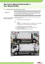
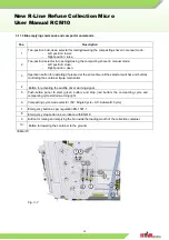
Page 26: ...achine operating status Layout of the command and control equipment A map showing the positioning of the command and control devices on the machine is given below 1 Command panel inside the driving cab NOTE Reference 1 illustrated in figure 3 5 shows one of the possible configurations of the command panel inside the driving cab 2 Two handed control for closing the rear door 3 Container emptying co...

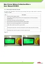
Page 27: ...king total hours the compression hours bin lifter working times discharge times 3 PTO button for turning on off the electrical system 4 Warning light turn on when driving and collection waste working 5 Main menu include the language selection and the signal data 6 Hatch button allows the operator to open the hatch 7 Discharge the waste button retracting or shaking the expulsion plate first and the...

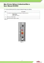
Page 28: ...ton panel in the container loading unloading zone left side Pos Description 1 Two handed control buttons for activating the following functions Plate retraction Hatch closure Safety latch insertion 2 Door open indicator light 3 Mushroom head emergency button Table 3 4 Fig 3 6 ...

Page 29: ...ressed at the same time all the selector switches and buttons controlling the container tip up mechanism 4 Button for activating the audible driver warning signal 5 Push button panel to start green button and stop red button the compacting cycle and compacting cycle started warning light 6 Compacting cycle mode selector SC Single Cycle AC Automatic Cycle 7 Emergency button as per regulation EN 150...

Page 30: ... NOTE The vehicle has not been subjected to any functional transformation by HYVA MECHANICS CHINA CO LTD so the user must refer to the manual supplied by the vehicle manufacturer with regards the instructions for using it ATTENTION The operator must possess a driving license valid for the country of use The operator must respect the highway code in force in the country of use ...

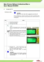
Page 31: ... supplied version the power take off can be activated directly via the main button panel Activating the power take off from the main button panel Activate the rotating beacon using the selector A Push the clutch down all the way Press button B to power on the electrical system and activate the power take off Release the clutch without engaging any pedal 3 Disengage the power take off after every m...

Page 32: ...PTO as far as step 2 then proceed as follows ATTENTION Check the parking brake is activated Step Action 1 After having exited the vehicle the operator must prepare the connection system and bring the bin near it 2 ATTENTION In order to avoid any residual risks that may be posed by the moving parts the operator must move to the control position A next to the collection tank thus distancing from the...

Page 33: ...t the same time as described in order to enable the consent function and the container s raising lowering and tipping phases ATTENTION Always carry out a sight control of container lifting and lowering operations If waste falls outside the tank or there are problems hooking up the container release one of the buttons immediately to stop the operations 4 Once the container emptying phase has been c...

Page 34: ...tarts the compacting cycle The indicator light next to the button C warns on the activation of the compacting cycle Fixed warning light Normal compacting cycle Flashing warning light Compacting blocked because the container is inside the loading mouth and the blade is in the idle position blade carriage in the front position To stop the compacting phase rotating the green button to 0 C The switchi...

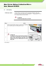
Page 35: ...he bin is to be unloaded Perform the operations described in paragraph 4 1 1 Engaging the PTO as far as step 2 then proceed as follows ATTENTION Check the parking brake is activated 2 Activate the parking brake Press the button A the hatch opening With exclusive reference to RCM10 equipment once the collection tank has been emptied in order to prevent any residual waste material from remaining ins...

Page 36: ...4 Go to the on board button panel in the container loading unloading area Press the two handed control buttons F to activate the following functions Expulsion plate retraction Hatch closure Rear edge safety latch insertion Hold down the buttons F until the indicator light E DOOR OPEN turns off 5 5 Disengage the power take off by pressing the clutch down fully until the indicator light G turns off ...

Page 37: ...on Micro User Manual RCM10 37 4 5 Leachate discharge manoeuvre Step Action 1 In order to discharge any leachate that may have accumulated inside the tank use the hose on the left or right hand side of the vehicle behind the cab ...

Page 38: ... outside the cab container emptying waste compacting hatch closure Functioning mode Description Semi automatic Safety regulations ATTENTION The semi automatic machine functions are activated by pressing the buttons or turning the corresponding selector switches on the command panels inside the driving cab and on the collection tank The activation of the various machine movements and functions must...

Page 39: ...closure stop Emergency stop The following tables show the procedures to be followed for each type of stop and the relative reset Type of stop Voluntary stop of the compactor Intervention Rotate the switch B to 0 position Reset The compacting shovel s movement can be reactivated by rotating the switch B to AUTO position NOTE When the compacting shovel s manual functionality is enabled its movement ...

Page 40: ...d by simultaneously pressing the consent button C and either button B or button A based on the movement to be performed Type of stop Voluntary hatch closure stop Intervention Release one of the two handed buttons being pressed G to stop the operations Reset The hatch closure movement which also causes the compacting plate to retract and the rear edge s safety latches to be inserted can be reactiva...

Page 41: ...ve the fault causing the safety intervention Restore the safety conditions necessary to restart working Reset the red mushroom button that has been activated by turning it clockwise and checking it rises from the stop position Power on the electrical system by pressing the button H on the control panel inside the cab Engage the power take off as described in section 4 1 1 Engaging the PTO Press th...

Page 42: ...nits involved in the intervention and any safety devices that have been disabled Regulations for personnel not authorised to carry out maintenance Unauthorised personnel must observe the following rules Avoid activating or tampering with the control equipment or tools on the machine without knowing how they work Keep away from the machine during maintenance or repair operations Regulations for res...

Page 43: ...orbidden for unauthorised personnel to intervene on the machine to force or remove the protection devices even during adjustment cleaning and maintenance operations In the event of malfunctioning of the safety devices ATTENTION Inform the section head immediately if you notice any malfunctioning of the safety devices or damage to the protection devices and interrupt all work in progress When carry...

Page 44: ...is powered It is absolutely forbidden to work on the moving parts for any reason whatsoever Before starting work stop the machine It is absolutely forbidden for unauthorised personnel to open the electric boxes For these operations contact the professionals authorised to intervene on the electric parts Replace the faulty parts with parts recommended by the manufacturer Products to be used for clea...

Page 45: ...tential risks for the operators and the machine itself Use of maintenance registers The use of maintenance registers is strongly recommended to establish the parts to be replaced and or component servicing intervals In addition these registers allow a maintenance programme to be drawn up in advance compatible with the use of the vehicles Types of recurrent maintenance intervention Recurrent mainte...

Page 46: ... 250 hours If any twisting stretching or breakage of the outer sheathing is encountered the cable must be replaced with one that has the same technical characteristics Verify the proper tightening of the equipotential connections every 1000 hours If any loose connections are encountered the proper tightening torque must be restored Visually inspect the inside of the electrical boxes every 250 hour...

Page 47: ...er the indicator on the filter itself is found to be in the RED sector Check the state of the flexible tubes Check the state of the hydraulic cylinders Perform a general inspection of the machine Grease the hinge points Check the pressure in the hydraulic system Check the state of the electrical cables Check the electric boxes Check the electrical connections Check the proper tightening of all the...

Page 48: ... 1 1 Polyurethane plate 3 560901515 2 1 1 Nylon wheel 560901515 7 2 2 Nylon sliding block left 560901515 8 1 2 Nylon sliding block right 560901515 9 1 2 Nylon stopper 560901516 0 2 4 External Circlips Type A 35 56968304 2 0 5 Nylon slider1 560901524 9 2 1 Nylon slider2 560901547 3 4 2 Lifting arm spring 560901025 0 2 0 2 Buffer block left 560901025 1 1 0 2 Buffer block right 560901025 2 1 0 2 Copp...

Page 49: ...6 4 1 Hose assy 1 2 HP 08 1500 01 91 160 16S 56286861 1 0 4 Hose assy HP06 2000 01 91 210Bar 12L 56286582 1 0 5 Hose assy 1 2 HP08 1600 01 91 315bar 16S 56286817 1 0 4 Hose assy 1 2 HP 08 650 01 01 315Bar 16S 56286716 2 0 5 Hose assy HP08 800 01 01 315 16S 56288271 2 0 5 Hose assy HP 08 800 01 91 250Bar 16S 56286678 2 0 5 Hose assy HP06 1100 01 91 315Bar 12L 56286609 4 1 Hose assy HP04 2700 01 01 ...

Page 50: ...ilgate opening cylinder 80 40 160 380 56214137 2 1 Packer cylinder 60 40 290 530 56214138 2 2 Slider cylinder 70 40 490 850 56214139 2 2 Locker cylinder 40 20 130 521 56214140 1 1 Lifting cylinder 1 60 35 379 624 56214141 1 1 Lifting cylinder 2 60 35 379 624 56214142 1 1 Turning cylinder 1 50 30 519 789 56214143 1 1 Turning cylinder 2 50 30 519 789 56214144 1 1 Lifting cylinder 40 20 142 273 56214...

Page 51: ...ight three position button M 3SS7 42G 20 56340769 1 0 3 Spiral cable 5 0 75 mm 56380361 1 0 2 Three holes control panel TLP3 B 56340701 1 0 2 Button box seat 16000061 56340702 1 0 1 Approximate sensor XS7E1A1PBM8 56340713 1 0 2 Approximate sensor IGS204 56380389 5 0 2 Position switch ZCKE05 56340720 1 0 2 Position switch ZCK J1 56340721 1 0 2 Position switch FR 531 PLZZATO 56340722 4 0 2 Magnetism...

Page 52: ...e oil Recommendations for annual average temperature below 20 Shell HM 32 anti abrade oil Grease Grease 1 2 3 Table 5 5 4 12 Maintenance operating instructions Introduction ATTENTION Before carrying out any operations check the machine is safely stopped disconnecting it from the power supply and switching off the vehicle engine Safety regulations for accessing the upper parts of the machine ATTENT...

Page 53: ...rrence every 100 h Clean the safety latch movement zone and eliminate any waste residues that may have been deposited in the area Proceed as follows Remove the protection element A by unscrewing and removing the fastening screws that hold it in place Eliminate any waste residues that may have been deposited in this area After having completed the cleaning operations re apply the protection element...

Page 54: ... follows ATTENTION Check the parking brake is activated NOTE Perform the inspection with all the hydraulic cylinders in their closed positions or rather with rods retracted Step Action 1 Check the indicator B to verify that the oil is at its maximum level MAX 3 Top it up using HM 32 anti abrade hydraulic oil only using the amount of oil necessary to bring it to the proper level which can be checke...

Page 55: ...e appropriate greasers or else by applying grease to the indicated points themselves The grease application points are listed below Case tipping rotation pins Case tipping piston pins Arm hinge pins for DIN BO and EUROPA type case tipping KR hatch opening piston pins KRM hatch opening piston pins Compacting shovel movement pins Compacting shovel rotation piston pins Structure subframe hinge pins E...

Page 56: ...Action 1 Place a container beneath the tank to collect the used oil Close the gate valve H on the tank s flange 2 Unscrew the band s tightening screw F and extract the flexible hose G to drain all the oil contained inside the tank Re open the gate valve H to allow the oil inside the tank to flow out into the container below 3 After having emptied the tank re insert the flexible hose G and secure i...

Page 57: ... sector or at least every 1000 hours of operation ATTENTION In order to verify the exact reading on the indicator L the hydraulic system must be maintained in function In order to perform these operations the cab must be tipped forward as this will facilitate the replacement operations Proceed as follows ATTENTION Check the parking brake is activated Step Action 1 Unscrew and remove the unloading ...

Page 58: ... be stored it must be positioned on flat ground asphalted if possible Safety warnings ATTENTION The user shall ensure all windows are closed engage the parking brake and lock the vehicle In the event of permanent non use WARNING It is a good idea to shelter the machine from atmospheric agents if it is not being used for a long time ...

Page 59: ... in force In any case it is absolutely forbidden to deposit it in the environment where it may pollute the groundwater table and the land Authorised personnel The machine must be scrapped by specialised electrical and mechanical personnel Preliminary operations to be carried out Before scrapping you must Disconnect the machine from all energy sources Disconnect the electrical cables leading to the...

Page 60: ...ective 2002 96 EC concerning waste electric and electronic equipment WEEE ATTENTION The user is obliged to send the equipment to the local collection centres authorised to treat and recover WEEE Failure to observe this regulation is a crime punishable by law NOTE If the user purchases a new EQUIVALENT device he can take the used equipment back to the manufacturer who is obliged to accept it and di...

Page 61: ...ntervention may be carried out by the operator this intervention may only be carried out by a specialised mechanical or electrical maintenance technician or the Hyva after sales service Preliminary operations to be carried out Before carrying out any type of check ensure the maximum working hydraulic pressure is 150 bar This is done in the following way Step Action 1 Please proceed as explained in...

Page 62: ...perations Disengage the PTO by pressing the clutch fully down Power off the electrical system by pressing button H WARNING Always disengage the PTO before resuming road transportation to avoid burning the hydraulic pump 7 WARNING The vehicle should only be driven off once the parking brake has been deactivated ...

Page 63: ...em remains pressurised verify the proper functionality of proximity sensor S3 on the upper part of the hatch shovel raised sensor If the system does not remain pressurised check to make sure that the single or automatic cycle selector on the external button panel is set to its single cycle position The shovel opens and closes without the carriage descending Check the carriage descent coil The shov...

Page 64: ...eck to make sure that the latch solenoid is not blocked and is receiving electrical power The latches do not close hatch blocked Check to see if the INPUT 8 is 1 in the display of cabin Check to make sure that the latch solenoid is not blocked and is receiving electrical power The hatch does not open Check to make sure that the latches retracted sensors SQ5 SQ6 hatch released are functioning prope...

Page 65: ...in tipping unit The bin tipper blocks the bin but does not perform the lifting operation Check to make sure that the raise container solenoid is not blocked and is receiving electrical power Check pressure switch SP4 on the solenoid valve unit Check to make sure that sensor S10 input 37 is 1 is on The container does not begin emptying once it arrives at the loading opening Check to make sure that ...

Page 66: ...ure 1 Plate limit switch SQ7 input 9 2 Hatch closed sensor S5 input 28 3 Hatch open sensor S4 input 29 4 Shovel raised sensor S3 input 11 5 Bin tipper ascent exchange sensor S9 input 36 6 Bin tipper at rest sensor S11 input 38 7 Bin tipper descent exchange sensor S10 input 37 8 Edge sensor S16 input 12 ...

Page 67: ...rmation as possible concerning such failure before you call us for service support Such information may include What category does the message appearing on the display belong to Which part of the equipment can work properly Which part of the equipment cannot work properly The more information concerning the equipment failure our service support personnel get the faster your installation operation ...

Page 68: ...Body size L W H mm 4890x1940x1800 Weight Superstructure Kg 3800 Body volume m 3 10 Compaction cycle time 14 Discharging time 70 Compaction ratio 1 2 5 Bin type EN 840 120L 240L 360L 660L 1100L Bin lifter cycle time Sec 19 Bin lifter capacity Kg 500 Voltage V 24 Hydraulic system pressure bar 200 Control mode Entry E ...

Reviews: