Chapter 4 - Drive Bay
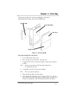
Removing/installing the floppy drive in the drive module
1.
Remove the floppy drive from the chassis.
2.
Remove the two screws securing the CD-ROM drive bracket to the
hard drive/floppy drive bracket (on the CD-ROM side of the bracket,
at the rear edge).
3.
Remove the three screws securing the hard drive/floppy drive bracket
to the front panel.
4.
Before physically separating the hard drive/floppy drive bracket from
the module, unplug the power and signal cables from the floppy drive
and the hard drive.
5.
Remove the four screws that mount the floppy drive to the
bracket, taking care not to lose any of the eight nylon shoulder wash-
ers.
Note:
These washers isolate the floppy drive case from chassis ground.
If they are not replaced in their proper positions, EMI/RFI integri-
ty may be compromised.
6.
Remove the floppy drive.
7. Place a new floppy drive on the bracket after first placing four shoul-
der washers in the drive mounting holes, with the flat washer-side
toward the floppy drive.
8.
Place the other four shoulder washers in the drive mounting holes,
with the flat washer-side toward the mounting screw head.
9.
Secure the floppy drive with the four screws removed in step 5.10.
10. Re-plug the power and data cables to the floppy drive and hard drive.
11. Secure the hard drive/floppy drive bracket to the drive module front
panel using the three screws removed in step 3.
12. Secure the hard drive/floppy drive bracket to the CD-ROM bracket
using the two screws removed in step 2.
13. Place the drive module back into the chassis.
14. Secure it by tightening the captive screws.
4-3
G8 CPCI Enclosure User’s Guide
Summary of Contents for G8
Page 1: ...G8 CPCI Enclosure User s Guide G8 8 Slot CompactPCI Enclosure User s Guide 095 30004 00 Rev A ...
Page 8: ...iv Table of Contents This page was intentionally left blank G8 CPCI Enclosure User s Guide ...
Page 20: ...2 8 G8 CPCI Enclosure User s Guide Chapter 2 Hardware This page was intentionally left blank ...

