16
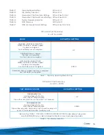
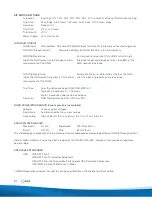
TABLE 1
Operating Mode Settings
DIP switch 1
TABLE 2
Trip Memory Selection
DIP switch 2
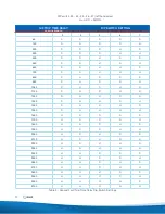
TABLE 3
Ground Fault Trip Time Delay Settings
DIP switches 3,4,5,6,7
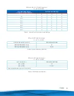
TABLE 4
Ground Fault Trip Current Level Settings DIP switches 8,9,10
TABLE 5
System Frequency Selection
DIP switch 11
TABLE 6
NGR Tolerance
DIP Switch 12
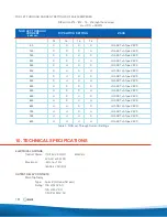
TABLE 7
NGR Let-through Current Settings
DIP switches 13,14,15,16
DIP switch #1 (left hand array)
U = UP, D = DOWN
FAILSAFE (UNDERVOLTAGE TRIP)
SIGMA-MD Relay is Idle/Not-Tripped:
Trip Relay is energized
Aux Fault Relays are not energized.
UP
SIGMA-MD Relay is Tripped:
Trip Relay is de-energized
Aux Fault Relays are energized
NON-FAILSAFE (SHUNT TRIP)
SIGMA-MD Relay is Idle/Not-Tripped:
Trip Relay is not energized
Aux Fault Relays are not energized
DOWN
SIGMA-MD Relay is Tripped: Trip Relay is energized
Aux Fault Relays are energized.
MODE
DIP SWITCH SETTING
Table 1 - Trip Relay Operating Mode Setting
TRIP MEMORY ON
Control voltage off after trip:
When Control voltage restored
Trip and Aux relays Idle* then re-trip (within 1 to 2 seconds).
UP
TRIP MEMORY OFF
Control voltage off after trip:
When Control voltage restored
Trip and Aux relays Idle* but do not re-trip Trip and Aux relays will
re-trip if a fault is detected after monitoring starts.
DOWN
* Idle state: See TABLE 1, TRIP RELAY OPERATING MODE SETTING for description of relay states
when the SIGMA-MD relay is idle/not-tripped for failsafe and non-failsafe operating modes.
TRIP MEMORY ON/OFF
DIP SWITCH SETTING
DIP switch #2 (left hand array)
U = UP, D = DOWN
Table 2 - Trip Memory Selection


