22
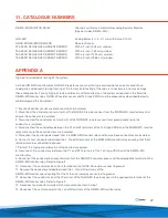
11. CATALOGUE NUMBERS
SIGMA-MD MONITOR RELAY
Ground Fault Relay & Neutral Grounding Resistor Monitor
(Special
Order:
SIGMA-MD)
GFU-AM1
Analog Meter, 3 ½ in. 0-1 mA with Scale 0-100%
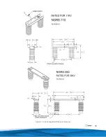
NGRS-XX RESISTOR SENSOR
Resistor Sensor
T2A ZERO SEQUENCE CURRENT SENSOR
With a 2 inch (5.08 cm) window.
T3A ZERO SEQUENCE CURRENT SENSOR
With a 3 inch (7.62 cm) window.
T6A ZERO SEQUENCE CURRENT SENSOR
With a 6 inch (15.24 cm) window.
T9A ZERO SEQUENCE CURRENT SENSOR
With a 9 inch (22.86 cm) window.
APPENDIX A
High-pot and dielectric testing of the system.
As the SIGMA-MD monitor relay, NGRS-XX resistor sensor and TxA type zero sequence current sensor have
undergone and passed high-pot testing at the factory, field testing of the relay is unnecessary and may damage
these components. For any high-pot tests or dielectric withstand tests on the system conducted in the field, the
SIGMA-MD monitor relay, NGRS-XX resistor sensor and TxA type ZSCS must be prepared as described below to
avoid damaging this equipment.
1. Ensure all control circuits are disconnected and insulated.
2. Disconnect the conductor on terminal R of the NGRS-XX resistor sensor from the SIGMA-MD monitor relay and
ensure the conductor is insulated.
3. Disconnected the conductor on terminal G of the NGRS-XX resistor sensor from ground and ensure the
conductor is insulated.
4. Disconnected the conductors between the X1 and X2 terminals of the TxA type ZSCS and the SIGMA-MD monitor
relay and ensure these conductors are insulated.
5. Disconnect the control power leads from the SIGMA-MD monitor relay and ensure these conductors are insulated.
6. Connect short conductors between the L, N and G terminals of the SIGMA-MD monitor relay ensuring that the G
terminal remains connected to ground.
7. Perform the high-pot or dielectric withstand tests required.
8. Reconnect the conductors between the X1 and X2 terminals of the TxA type ZSCS and the SIGMA-MD
monitor relay.
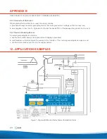
9. Reconnect the conductor between terminal G of the NGRS-XX resistor sensor and the appropriate terminal on the
SIGMA-MD monitor relay. Refer to Figure 2.
10. Reconnect the conductor from the G terminal on the NGRS-XX resistor sensor to ground.
11. Remove the conductors added between the L, N and G terminals of the
SIGMA-MD monitor relay ensuring that the G terminal remains connected to ground.
12. Reconnect the conductor from the R terminal of the NGRS-XX resistor sensor to the appropriate terminal of the
SIGMA-MD monitor relay. Refer to Figure 2.
13. Reconnect and control circuits which were disconnected in step 1.
14. Reconnect the control power to the L and N terminals of the SIGMA-MD monitor relay.


