User Manual
BOP HD8 / BOP HD16
Ref.: IR1212828 A 21.08.2009
Edition 1.0
Page 13/87
I + M E A C T I A G m b H
2.1
F
RONT SIDE
-
BOP
HD
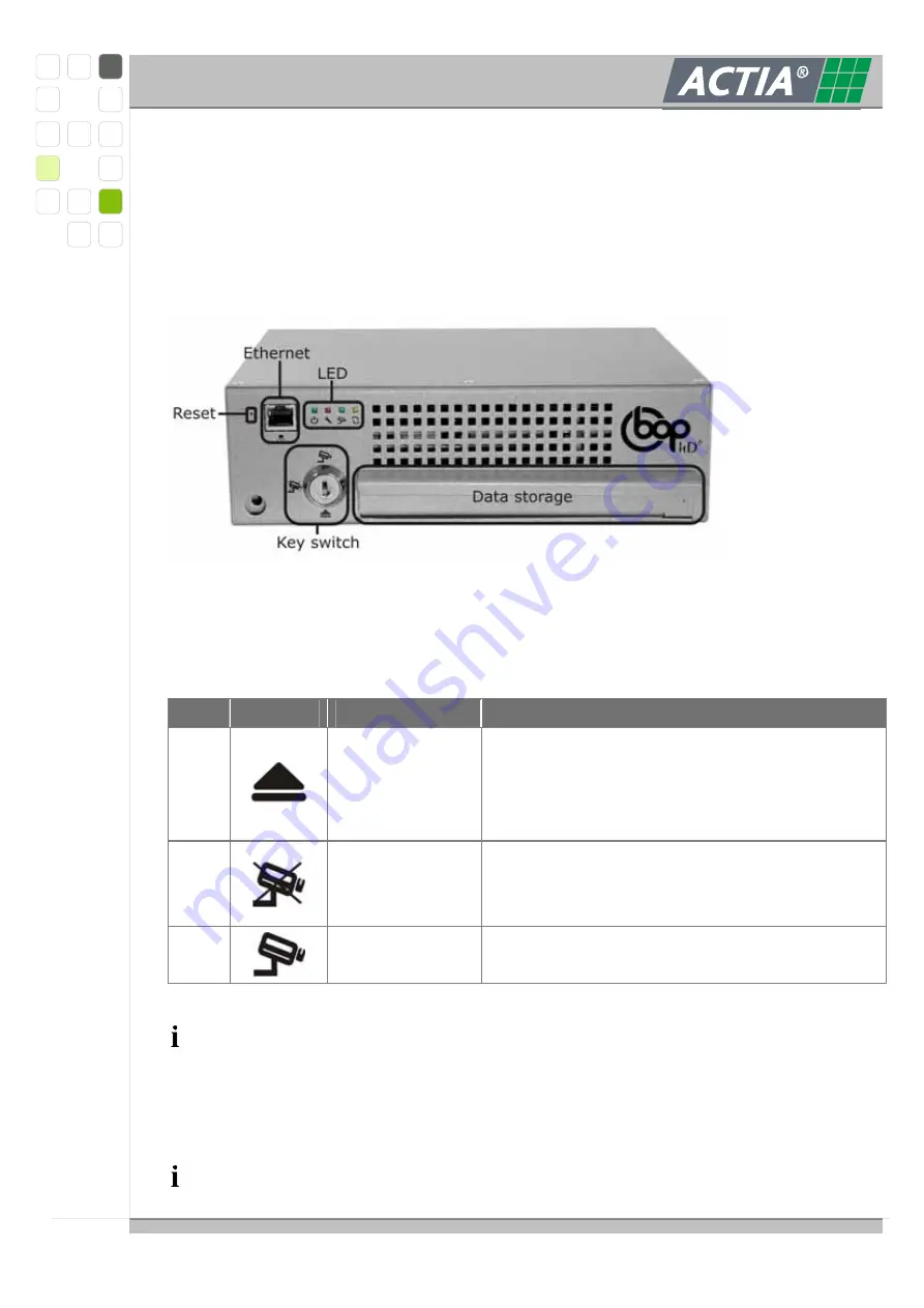
At the front panel all control elements and gauges are arranged. The Ethernet connector
for configuration and maintenance is also placed at the front panel. Normally after the
integration the BOP HD must not dismounted for maintenance and configuration.
2.1.1.
K
EY SWITCH
By the key-switch the BOP HD is set to the following operation modes.
Pos.
Symbol
Mode
Note
1
OFF
The BOP HD is off/ is switched off.
After the automatically disabling of the
electromagnetic locking the data storage could
be detached.
2
PAUSE
The BOP HD switches offline.
No data will be recorded.
For maintenance and reviewing.
3
RECORD
The BOP HD records video and audio data
according to the settings in the configuration.
Only authorized staff may switch the mode.
Remove the key-switch to protect prior unauthorized change of the operation
mode.
At switch-on a self test is executed (from >OFF< to >PAUSE< or >AUFNAHME<).


