background image

EMS i-MO 210 C Series Hardware Installation Guide


Version 

1.0


ELECTRONIC MEDIA SERVICES LIMITED


1st Floor, Building 51, Whitehill & Bordon Enterprise Park, Budds Lane, Bordon, Hampshire, GU35 0FJ 

Tel:

 01428 751655 | 

Fax:

 01428 751654 | 

E-mail:

 imo@ems-uk.com


Page 

11

 of 

16


Connect the equipment into an outlet on a circuit different from that to which the receiver is 
connected. 


Consult the dealer or an experienced radio/TV technician for help. 

CAUTION: Any changes or modifications not expressly approved by EMS Ltd could 

void the user’s authority 

to operate the equipment. 

This device complies with Parts 15 and 27 of the FCC Rules. Operation is subject to the following two 
conditions: (1) This device may not cause harmful interference, and (2) this device must accept any 
interference received, including interference that may cause undesired operation. 

Certification Information (SAR) 

Your wireless device is a radio transmitter and receiver. It is designed not to exceed the limits for exposure to 
radio waves recommended by international guidelines. 

These guidelines are developed by the independent scientific organization International Commission on 
Non-ionizing Radiation Protection (ICNIRP) and include safety margins designed to assure the protection of 
all persons, regardless of age and health. 

The guidelines use a unit of measurement known as the Specific Absorption Rate,  or SAR. The SAR limit for 
wireless devices is 2.0 watts/kilogram (W/kg) and the highest SAR value for this device when tested 
complies with this limit. 

Important safety information regarding radio frequency (RF) radiation exposure is as follows: 

To ensure compliance with RF exposure guidelines, the device must be used with a minimum of 2.5cm 
distance from the body. Failure to observe these instructions could result in your RF exposure exceeding the 
relevant guideline limits. 

Technical Data 


2412 ~ 2472, 2484 MHz (subject to local regulations) 


Modulation Technology OFDM and DSSS 


Modulation Techniques 64QAM, 16QAM, QPSK, BPSK, CCK, DQPSK, DBPSK 


Data Rates 54, 48, 36, 18,12, 9, 11, 6, 5.5, 2, and 1 Mbps, auto fallback 


Peak Output Power Targeted at 14dBm @54Mbps, 18dBm @11Mbps 


Minimum Receive Sensitivity Targeted at -70dBm @54Mbps; -80dBm@11Mbps 


Antenna - default attached Stub antenna with the gain of 2.2 dBi. 

Safety Regulation and Operating Environment 


EMC certification 


CE (Europe) 


Temperature Range Operating: 0 ~ 45 degree C, 


Storage: -20 ~ 60 degree C 


Summary of Contents for OptiBond 210 C Series

Page 1: ...Hardware Installation Guide i MO 210 C Series Bonding Router Hardware Installation Guide for the i MO 210 C Series Appliance...

Page 2: ...w to attach the WiFi antenna 7 2 How to attach the 3G 4G antennas 7 3 How to attach network and ADSL cables optional 8 4 How to install SIM cards optional if not already fitted 8 5 How to attach the p...

Page 3: ...ITED 1st Floor Building 51 Whitehill Bordon Enterprise Park Budds Lane Bordon Hampshire GU35 0FJ Tel 01428 751655 Fax 01428 751654 E mail imo ems uk com Page 3 of 16 I MO Appliance Identification Guid...

Page 4: ...remove chassis covers or sheet metal parts unless instructions are provided in this documentation Such an action could cause severe electrical shock Do not push or force any objects through any openi...

Page 5: ...ground conductor for each data signal when applicable Electromagnetic Compatibility If your site is susceptible to problems with electromagnetic compatibility EMC particularly from lightning or radio...

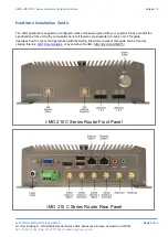
Page 6: ...uide The i MO appliance is supplied un configured unless otherwise agreed with your supplier Please confirm the specification of the unit with your supplier as not all features are supported on every...

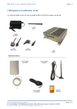
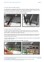
Page 7: ...Note Connectors should be touch tight only Do not over tighten 2 How to attach the 3G 4G antennas The i MO 210 C Series 4G Router appliance is normally supplied with a minimum of 2 of 3G 4G aerials A...

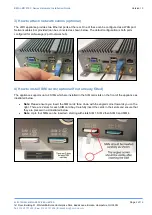
Page 8: ...n be connected as shown below The default configuration is both ports configured for LAN usage 2 port network hub 4 How to install SIM cards optional if not already fitted The appliance supports up to...

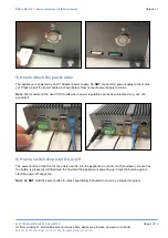
Page 9: ...the mains yet Please insert the power cable as shown below Now connect power supply to mains Note We recommend the use of UPS units where power regulation cannot be guaranteed e g use of a generator 6...

Page 10: ...lectromagnetic Fields 3kHz to 300 GHz National Council on Radiation Protection and Measurements NCRP Report 86 1986 Biological Effects and Exposure Criteria for Radio Frequency Electromagnetic Fields...

Page 11: ...fic organization International Commission on Non ionizing Radiation Protection ICNIRP and include safety margins designed to assure the protection of all persons regardless of age and health The guide...

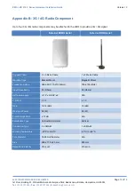
Page 12: ...External MIMO Aerial External ROD Aerial Supplied Cable 2 x 5 Metre Cable 1 x 5 Metre Cable Mounting Type Bracket Mount Magnetic Mount Frequency Range 698 960 1710 2700 MHz 700 2700 MHz Input Impenden...

Page 13: ...p immediately Choosing a Mounting Location The location of the antenna is important Objects such as metal columns walls etc will reduce efficiency Best performance is achieved when antennas are mounte...

Page 14: ...osal of this device is subject to the Waste from Electrical and Electronic Equipment WEEE directive of the European Union The reason for separating WEEE and batteries from other waste is to minimize t...

Page 15: ...ponsible for paying all parts labour and shipping charges The warranty described above shall apply to all repaired or replaced Product for a period of 90 days from the date of return to you or the bal...

Page 16: ...HAS BEEN ADVISED OF THE POSSIBILITY OF SUCH DAMAGES OR THEY ARE FORESEEABLE OR FOR CLAIMS BY ANY THIRD PARTY MAXIMUM AGGREGATE LIABILITY OF THE AFOREMENTIONED PERSONS SHALL NOT EXCEED THE AMOUNT PAID...

Reviews: