background image

4

5

1.5 Introduction to the Smart Panel sound alert and backlight

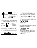
•  Tape the template onto the wall, in the position you wish to install the Smart Panel.

•  Mark on the wall the points for drilling holes for the wall plugs and mounting screws, and the position 

for mounting the tamperproof magnet.

•  Drill the holes, insert wall plugs and locate the mounting screws for the Smart Panel.

• Ensure the mounting surface for the tamperproof magnet is clean.

•  Peel back one layer of the protective film on the double-sided adhesive strip and attach it to the 

magnet.

•  Peel back the remaining layer of protective film and press the magnet firmly in the marked position 

against the mounting surface until firmly attached

• Mount the wSmart Panel onto the wall.

•  Once the Smart Panel has been installed the system can be powered up. The tamperproof system is 

enabled once the Smart Panel is switched to HOME, ALERT or ARM mode.

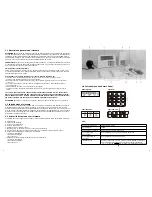
2.2 Powering up the Smart Panel controller

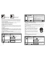
Note: 

The Smart Panel is supplied with a demonstration switch to show the LCD display panel wor

-

king whilst the unit is in its packaging. Before powering up the Smart Panel the wire for this switch 

must be removed as described below (See Figs 1 & 2):

• Unscrew the battery compartment and remove the cover.

• Remove and discard the LED demo socket, if fitted (Fig. 2).

•  Insert a new back-up battery (noting the polarity) and plug the AC adaptor into the Smart Panel 

(Fig. 3).

•  Replace the cover and screw, and connect the AC adaptor to a wall socket. (Fig. 4).

2.1 Installing the Smart Panel

WARNING:

 The i.onik

®

 Smart Panel has a built-in tamper-proof switch to prevent the system being 

disabled by an intruder. When fixing the Smart Panel to a wall, first ensure that it is in Standby mode 

to avoid the alarm sounding.

2.1.1 Locating the Smart Panel and tamperproof switch

Determine the location of the Smart Panel, which should be placed:

- within a few feet of an electrical outlet

- where it is easily accessible

- away from doors or windows that could be accessed by intruders

-  way from extreme temperature sources (radiators, ovens, stoves etc.) and large metal objects that 

could interfere with the wireless performance

2.1.2 Wall mounting the Smart Panel and tamperproof switch

•  First cut out the mounting template for the Smart Panel along with the area which is marked out 

for the position of the tamperproof magnet (see below).

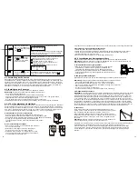
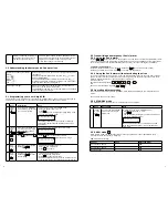
Operating 

Mode

Situation

Sound alert and backlight indication

1

ARM

Zone triggered

under ARM 

status

Alarm duration: Adjustable between 1 – 6 minutes (siren).

Default is 1 minute Smart Panel – flashes red every 


1.5 seconds with triggered zone indicated (To stop – enter 

4-digit PIN and press 

).

Alarm set under

ARM status

No siren

Smart Panel – flashes RED every 5 seconds providing an

intruder deterrent (different from when an intrusion occurs 

and the panel rapidly and continuously flashes red).

2

HOME

Zone triggered 

under ARM 

status

Alarm duration: Adjustable between 1 – 6 minutes (siren).

Default is 1 minute.

Smart Panel – flashes red every 1.5 seconds with triggered

zone indicated (To stop – enter 4-digit PIN and press 

).

Zone triggered

under ALERT

status

Sound output: Chime (ding-dong)

Smart Panel – flashes green every 1.5 seconds with triggered

zone indicated (To stop panel flashes - press 

).

3

ALERT

Zone triggered

under ALERT

status

Sound output: Chime (ding-dong)

Smart Panel – flashes green every 1.5 seconds with triggered

zone indicated (To stop panel flashes press 

).

4

STANDBY

Silent

Smart Panel – yellow backlight remains ON for 10 seconds

after entering into STANDBY mode.

Mount tamperproof magnet here

84mm

62m

m

43m

m

16mm

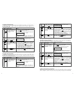
Step

Description

Note

1

Insert 9V Alkaline backup battery

One beep will sound and the backlight will blink

within 1 second (Yellow

Red

Green

Yellow)

The Smart Panel will display the below image:


The Smart Panel will enter “STANDBY” mode after 

the automatic self-checking is complete. Then will 

appear on the LCD screen.

Enter the default 4-digit PIN “1234”

Fig. 1 (WS-101)

Fig. 3 (WS-101)

Fig. 4 (WS-101)

Fig. 2 (WS-101)

9V battery

WS-101

WS-102

WS-103

Summary of Contents for WS-100

Page 1: ...9 0 180 5000251 Email support i onik de 0 14 min Bei Anrufen aus dem Mobilfunknetz kann der Preis abweichen 0 14 min For calls from mobile phones the price may vary Weitere Informationen und Erkl rung...

Page 2: ...Abb 6 Bewegungsmelder Ben tigt 9 V Batterie nicht enthalten Entfernen Sie die Abdeckung legen Sie eine neue 9 V Batterie ein und achten Sie dabei auf die Polung Abb 2 Setzen Sie dann die Abdeckung wie...

Page 3: ...lgt von um den ALERT Modus zu verlassen Fernbedienung Um den Modus zu verlassen dr cken Sie die entsprechende Taste auf der Fernbedienung 8 Den akustischen Countdown stummschalten Wenn das Smart Panel...

Page 4: ...pear Step 2 Press then to enter Remote Control Enrol mode Step 3 Then press any key on the Remote Control to enrol it onto the system Step 4 Press to complete the enrolment 9 V battery 6 Operating the...

Page 5: ...h Chips and More GmbH Gewerbestr 7 79112 Freiburg Germany www i onik de Service 49 0 180 5000251 Email support i onik de 0 14 min Bei Anrufen aus dem Mobilfunknetz kann der Preis abweichen 0 14 min Fo...

Page 6: ...tig funktionieren Obwohl der Besitz einer Alarmanlage die Versicherungspr mien reduzieren kann ist eine Alarmanlage kein Ersatz f r eine Versiche rung WARNUNG Alarmanlagen k nnen den Verlust von Eigen...

Page 7: ...dose gelegen leicht zug nglich von T ren und Fenstern die leicht von einem Einbrecher zu erreichen sind entfernt weit genug entfernt von extremen W rmequellen Heizungen Ofen Herd usw und gro en Metall...

Page 8: ...BY Modus Wenn sich das Smart Panel im STANDBY Modus befindet kann der Modus ausgew hlt werden 3 3 2 ARM Modus Wenn sich das Ger t im ARM Modus befindet ert nt die Smart Panel Sirene und das Smart Pane...

Page 9: ...merkung 1 1234 4 stelli ge PIN Das Ger t muss sich im STANDBY Modus befinden bevor Sie die Dauer des Alarms einstellen k nnen Um sicher zu stellen dass sich das Ger t im STANDBY Modus befindet Geben S...

Page 10: ...nden Es besteht eine 15 Sekunden lange Verz gerung mit sichtbarem und h rbarem Countdown bis das System eingeschaltet ist Dr cken Sie MUTE um diesen Countdown zu deaktivieren Sobald die Zone aktiviert...

Page 11: ...den bevor Sie den ALERT Modus einstellen k nnen Sie m ssen im STANDBY Modus sein Um sicher zu stellen dass sich das Ger t im STANDBY Modus befindet Geben Sie die Standard PIN 1 2 3 4 ein Dr cken Sie D...

Page 12: ...Klebestreifen Stellen Sie sicher dass der Untergrund sauber ist Ziehen Sie eine Seite des Schutzfilms ab und befestigen Sie den Klebestreifen an dem Sender Ziehen Sie die zweite Seite des Schutzfilms...

Page 13: ...dem LCD Bildschirm des Smart Panels blinkt und zeigt die ausgel ste Zone an HOME Wenn Sie die HOME Taste auf der Fernbedienung dr cken schalten Sie das System in den Home Modus wodurch das System ver...

Page 14: ...es den angerufenen Personen den Vorg ngen im Haus zuzuh ren und mit den Personen zu sprechen um die Situation besser einsch tzen zu k nnen Der automatische Notrufnummernw hler Panikalarm funktioniert...

Page 15: ...der automatische Notrufnummernw hler funktioniert muss er mit einer Telefonleitung verbunden werden ffnen Sie das Batteriefach um die 2 Steckdosen f r das Telefonkabel freizulegen Verbinden Sie die Li...

Page 16: ...nn kann der W hlvorgang nur durch das Unterbrechen der Stromversorgung zum automa tische Notrufnummernw hler und das Ausstecken der Batterie verhindert werden 5 4 3 Die Verbindung nach dem Gespr ch BE...

Page 17: ...mit dem System auftreten k nnen wenn die Sensoren nicht in H rweite von schlafenden Personen oder entfernt gelegenen Teilen des Geb udes platziert werden die Sensoren hinter T ren oder anderen Hindern...

Page 18: ...VDC PIR Erfassungsreichweite H 15M M 6M L 4M Hauscode 4 Steckschalter Zonencode Stiftleiste 8 Stifte Drahtlose Reichweite zum Smart Panel 250 Meter Freifl che Energiespartimer 3 Minuten 7 2 5 Automati...

Page 19: ...1 hometec hometec WS 200 Wireless Alarmsystem Manual Chips and More GmbH Gewerbestr 7 79112 Freiburg Germany www i onik de English...

Page 20: ...sensors and siren s are working properly Although having an alarm system may make you eligible for reduced insurance premiums the system is no substitute for insurance WARNING Security system devices...

Page 21: ...al outlet where it is easily accessible away from doors or windows that could be accessed by intruders way from extreme temperature sources radiators ovens stoves etc and large metal objects that coul...

Page 22: ...stem has 4 operating modes STANDBY ARM ALERT and HOME to suit individual require ments These modes can be set as follows 3 3 1 STANDBY mode If in STANDBY mode the Smart Panel is prepared for mode sele...

Page 23: ...to STANDBY by pressing Keys Description Note 1 1234 4 digit PIN You must be in STANDBY mode before adjusting the Alarm Duration To make sure you are in STANDBY mode Enter the default PIN 1 2 3 4 OR yo...

Page 24: ...a 15 second exit delay time with a visual and audible beeping countdown before the system is armed Press MUTE to disable the beeping countdown press MUTE again to resume the beeping If the Zone is ena...

Page 25: ...PIN You must be in STANDBY mode before turning to ALERT mode You must be in STANDBY mode To make sure you are in STANDBY mode Enter default PIN 1 2 3 4 OR your new 4 digit PIN Press The Smart Panel w...

Page 26: ...surface until firmly attached Repeat to attach the magnet 4 2 2 Installing the Motion Sensor The Motion Sensor is designed to sense movement in a given area Note It is best if pets are not allowed ont...

Page 27: ...the Smart Panel To make sure you are in STANDBY mode Enter the default PIN 1 2 3 4 OR your new 4 digit PIN Press The Smart Panel will display the image below when you are in STANDBY mode One beep indi...

Page 28: ...essed For installation and proper use of the Auto Dialler please familiarise yourself with this User Guide Instructions on programming the Auto Dialler are contained in the Quick Start Guide section 5...

Page 29: ...cipient should disconnect the call by pressing instead of just hanging up the phone This will terminate the connection for all existing call and the remaining calls Step 1 Enter SETUP mode for prior t...

Page 30: ...200 is designed for easy installation This means that the wireless sensors are in a default setting already registered to the Smart Panel and will therefore function immediately after the sensors are...

Page 31: ...ies regardless of the code selected A receiver can only respond to one transmitted signal at a time Wireless equipment should be tested regularly to determine whether there are sources of interfe renc...

Page 32: ...1 hometec hometec WS 200 Wireless Alarmsystem Manuale Chips and More GmbH Gewerbestr 7 79112 Freiburg Germany www i onik de Italiano...

Page 33: ...rme potrebbe rendervi idonei a premi assicurativi pi bassi il sistema non costituisce un sostituto all assicurazione stessa ATTENZIONE I sistemi si sicurezza non possono risarcire in caso di perdita d...

Page 34: ...ente facilmente accessibile lontana da porte o finestre che potrebbero fungere da accesso per gli intrusi lontano da fonti di calore radiatori forni stufe ecc e da oggetti metallici voluminosi che pot...

Page 35: ...verse modalit Il sistema dotato di 4 modalit operative STANDBY ARM ALERT e HOME per adattarsi alle esigen ze individuali Queste modalit possono essere impostate come segue 3 3 1 Modalit STANDBY Se in...

Page 36: ...l in STANDBY premendo Tasti Descrizione Nota 1 1234 PIN a 4 cifre necessario essere in modalit STANDBY prima di regolare la Durata d Allarme Per assicurarvi che la modalit STANDBY sia inserita Digitat...

Page 37: ...la rovescia visibile e udibile bip prima che il sistema sia azionato Premete MUTE per disattivare il bip del conto alla rovescia premete MUTE nuovamente per riattivarlo Se la Zona attivata un numero a...

Page 38: ...essario essere in modalit STANDBY prima di selezionare la modalit ALERT necessario che la modalit STANDBY sia inserita Per assicurarvi che la modalit STANDBY sia inserita Digitate il PIN di default 1...

Page 39: ...strato di pellicola protettiva rimanente e premete energicamente il trasmettitore sulla superficie di fissaggio finch non risulta saldamente attaccato Ripetete la stessa operazione con il magnete 4 2...

Page 40: ...o sullo Smart Panel Per assicurarvi che la modalit STANDBY sia inserita Digitate il PIN di default 1 2 3 4 Premete Lo Smart Panel mostrer l immagine in basso quando la modalit STANDBY inserita Un bip...

Page 41: ...ascoltare cosa in atto in casa e di parlare per capire meglio sulla natura dell emergenza Il dispositivo di chiamata automatica Allarme d emergenza pu sia funzionare in maniera indipen dente che in c...

Page 42: ...mpare FAIL significa che la linea telefonica non collegata correttamente o la connessione telefonica non valida Controllate la connessione Se la qualit di registrazione bassa registrate un nuovo messa...

Page 43: ...nte scollegan do il dispositivo di chiamata automatica dalla corrente elettrica e scollegando la batteria di supporto 5 4 3 DISCONNETTERE tutte le chiamate dopo la conversazione Finita la conversazion...

Page 44: ...stemi d allarme possono essere compromessi o soggetti a possibili mancati allarmi per diversi motivi Si potrebbero riscontrare problemi con il vostro sistema d allarme se I sensori non sono posizionat...

Page 45: ...rt Panel 250 metri spazio aperto Timer risparmio energetico 3 minuti 7 2 5 Dispositivo di chiamata automatica Fonte d alimentazione Adattatore AC Alimentazione di supporto Batteria alcalina AA x4pz Co...

Page 46: ...1 hometec hometec WS 200 Wireless Alarmsystem Manuel Chips and More GmbH Gewerbestr 7 79112 Freiburg Germany www i onik de Fran ais...

Page 47: ...n de vous assurer que les capteurs et la ou les sir ne s fonctionnent correctement Bien qu un syst me d alarme puisse vous rendre ligible des primes d assurances r duites le syst me ne peut se substit...

Page 48: ...fen tres qui peuvent tre accessibles par les intrus loign des sources de temp ratures extr mes radiateurs fours cuisini res etc et des grands objets m talliques qui peuvent interf rer avec la perform...

Page 49: ...DBY ARM ALERT et HOME afin d adapter les demandes individuelles Ces modes peuvent tre param tr s de la fa on suivante 3 3 1 Mode STANDBY Le Smart Panel est pr par pour le mode de s lection s il est en...

Page 50: ...r Touches Description Remarque 1 1234 Code PIN 4 chiffres Vous devez tre en mode STANDBY avant d ajuster le d lai d entr e Assurez vous que vous tes en mode STANDBY Entrez le code PIN par d faut 1 2 3...

Page 51: ...jusqu 15 secondes Il y a un temps de sortie de 15 secondes avec un compte rebours visuel et sonore biper avant que le syst me soit arm Appuyez sur MUTE pour d sactiver le compte rebours par biper app...

Page 52: ...en STANDBY mode STANDBY avant de passer en mode ALERT Vous devez tre en STANDBY Assurez vous que vous tes en mode STANDBY Entrez le code PIN par d faut 1 2 3 4 OU votre nouveau code PIN 4 chiffres App...

Page 53: ...m de protection et le fixer l metteur Retirer la couche du film de protection restante et appuyer fermement sur l metteur sur l emplacement marqu contre la surface de montage jusqu ce qu il soit ferme...

Page 54: ...rte de l affichage LED du Smart Panel clignotera et indiquera la zone d clench e HOME En appuyant sur la touche HOME de la t l commande celle ci placera le syst me en mode HOME lequel exploitera le sy...

Page 55: ...de parler la maison pour gagner une meilleure compr hension de la nature de l urgence L Auto Dialler alarme de d tresse peut galement fonctionner ind pendamment ou en association avec le syst me d ala...

Page 56: ...rder la prise Line votre prise jack murale de t l phone Raccorder la prise Phone de votre t l phone qui partagera donc votre ligne t l phonique avec l Auto Dialler Les fonctions normales du t l phone...

Page 57: ...connectant l alimentation principale de l Auto Dialler et en d con nectant l arri re de la batterie 5 4 3 Pour D CONNECTER tous les appels apr s la conversation D s que la conversation avec le haut p...

Page 58: ...iff rentes raisons Veuillez noter que vous pouvez rencontrer des probl mes avec votre syst me si Les capteurs ne sont pas plac s port e des personnes qui dorment ou des parties distances des locaux Le...

Page 59: ...C Port e de d tection PIR H 15M M 6M L 4M Code maison 4 jumpers Code zone Broche Port e sans fil 8 pins jusqu au Smart Panel 250 m tres espace ouvert Minuteur d conomie d nergie 3 minutes 7 2 5 Auto D...

Reviews: