2
CONNECTORS AND CONTROLS
Rear Panel
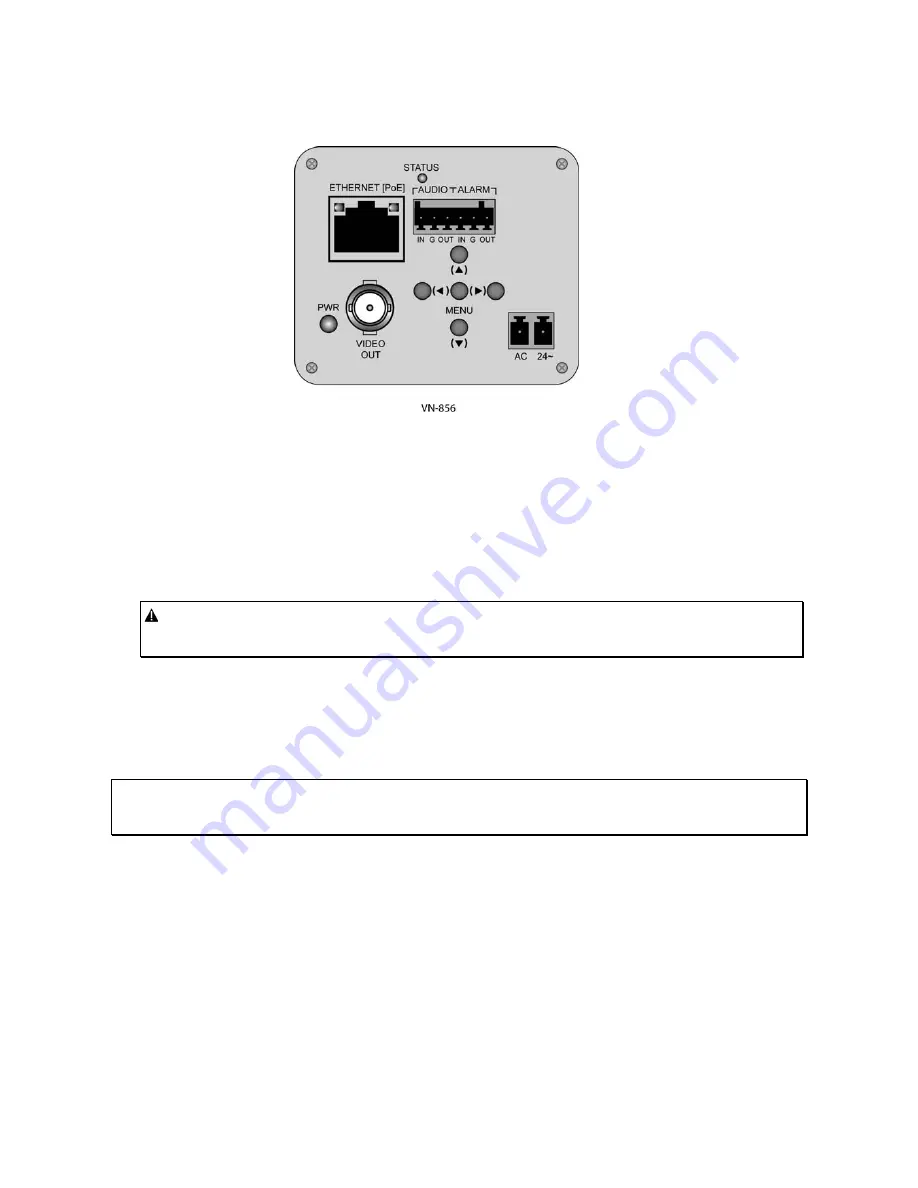
1. ETHERNET (Network Port)
RJ-45 port provides connection (RJ-45 connector) to Internet, Ethernet (10Base-T/100Base-T). The
green LED indicates that there is connection to the Network. This connection also provides PoE (Power
over Ethernet). When using PoE, a PoE device, such as the NETSWITCHPOE-24, is required.
2. POWER
A 2-pin screw terminal for 24 VAC connection. A red LED indicates that there is power to the camera.
Caution: To prevent fire or shock hazard, UL Listed wire VW-1, style 1007 should be used for the
cable for 24 VAC input terminal.
3. ALARM (Alarm Input) and AUDIO (Microphone)
This terminal block input provides 1 alarm and 1 audio input to the camera.
ALARM (Alarm Output)
can be defined in the ViconNet application as a relay. It can be set as ON-High,
OFF – Low or Momentary (momentarily ON).
Note: To connect to a relay device, the electrical specifications are: open-drain output accepts voltages up to
5.5 V, 24 mA output drive at 3.3 V, non-inductive.
4. VIDEO OUT
1.0 V p-p/75 ohm composite video signal is provided at this BNC connector.
5. MENU BUTTONS
– (Menus vary according to model)
Menu selections are model dependant. Refer to the OSD Menu section that follows.
XX181-10-02 Rev 110 VN-856V5 IP Camera


