background image


MINIFLEX 3-BFNH Instruction Manual


Document No. 

HIM-14004


9

  / 

12


Confidential C                                                                   

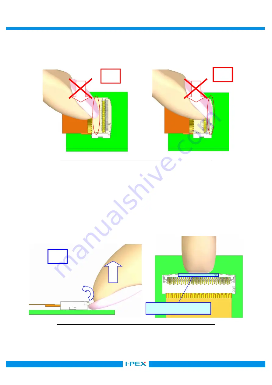
        ・ロック後にハウジング上面やアクチュエータを 10N 以上で押さえつけないで下さい。 
          コネクタ破損や FPC へダメージを与え、導通不良になる恐れがあります。 
            Please do not press at 10N or more housing on top and actuator after a lock actuator.     

Connector and FPC are damaged.    It becomes the electrical connection NG. 


図 14  アクチュエータのロック方法  (NG) / Fig.14 To lock actuator (NG) 


        ・ピンセット等の鋭利な工具を使用して操作しないで下さい。  コネクタを傷つける恐れがあります。 
          Please do not operate it using a sharp tool. (For example, tweezers)    Connector is damaged. 


4.  アクチュエータの解除方法/To release actuator 

アクチュエータの中央部を上に軽く跳ね上げる様に引き上げて下さい。 
Raise the center of actuator upwards lightly. 


図 15  アクチュエータの解除方法  (OK) / Fig.15 To release actuator (OK) 


OK 

NG 

NG 

操作部/Operation area 

Summary of Contents for 20613-0 E-0 Series

Page 1: ...E 0 20605 0 E 0 LONG ACT TYPE 20660 0 E 01 L HD TYPE 20780 0 E 01 L HD B TYPE Instruction Manual 5 S19621 October 2 2019 R Morita T Masunaga H Ikari 4 S18796 December 19 2018 H Aoki M Muro Y Shimada...

Page 2: ...afely Connector Product Name MINIFLEX 3 BFNH Part No 20613 0 E 0 20605 0 E 0 LONG ACT TYPE 20660 0 E 01 L HD TYPE 20780 0 E 01 L HD B TYPE part shows the number of the connector position Names of each...

Page 3: ...orce rises in inserting FPC because the gap of contacts became narrowed FPC FPC Even if the actuator is locked without FPC FPC is not inserted there is no remarkable affect to the contact pressure and...

Page 4: ...e connector Please confirm FPC is inserted into the end of mating part fully 3 FPC OK Fig 3 FPC insertion OK Caution 4 FPC If it becomes the short insertion and oblique insertion of FPC as shown in Fi...

Page 5: ...check of FPC insertion becomes easy by preparing the wing in FPC and preparing the silk print in board 5 FPC Fig 5 The check of FPC insertion Reference 6 FPC OK Fig 6 FPC insertion OK NG Short insert...

Page 6: ...ush against housing both ends at 5N or more Housing is damaged 8 FPC NG Fig 8 FPC insertion NG FPC FPC Please do not press FPC near a connector Contact gives damage to FPC and contact is damaged It be...

Page 7: ...uator to the arrowed direction horizontally with finger cushion from the FPC inserting direction 10 OK Fig 10 To lock actuator OK Caution Please do not press an actuator from a top and lock actuator b...

Page 8: ...ential C Please do not operate side of an actuator Actuator is damaged or it becomes imperfect lock 12 NG Fig 12 To lock actuator NG Please do not press contact on top by finger nail etc after a lock...

Page 9: ...ator after a lock actuator Connector and FPC are damaged It becomes the electrical connection NG 14 NG Fig 14 To lock actuator NG Please do not operate it using a sharp tool For example tweezers Conne...

Page 10: ...en release actuator is difficult raise the center of actuator upwards lightly using the following JIG 16 OK Fig 16 To release actuator OK Caution FPC Please do not press to the direction of FPC mating...

Page 11: ...l For example tweezers Connector is damaged 5 FPC Flexion of FPC FPC FPC Please bend from the end of FPC stiffener 19 FPC OK Fig 19 Flexion of FPC OK Caution FPC FPC FPC Please avoid applying excessiv...

Page 12: ...6 Regarding board warp after mounting 90mm PCB 0 5mm JEITA ED 4702C Be careful that warp of 90mm width PCB is 0 5mm or less If excessive warp is applied Connector is damaged Reference standard JEITA...

Reviews: