

MINIFLEX 2-BF Instruction Manual
Document No.
HIM-16031
10
/
12
Confidential C
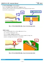
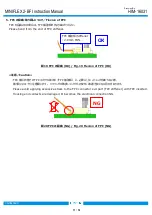
≪注意/Caution≫
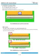
・アクチュエータを解除する際、FPC 嵌合側に押さえつけないで下さい。
アクチュエータの破損やコンタクトの変形が発生する恐れがあります。
Please do not press to the direction of FPC mating side.
Actuator and contacts are damaged.
図 17. アクチュエータの解除方法 (NG) / Fig.17 To release actuator (NG)
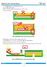
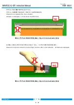
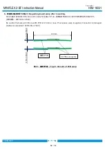
・アクチュエータの片端部で操作をしないで下さい。 アクチュエータが破損する恐れがあります。
Please do not operate side of an actuator. Actuator is damaged.
図 18. アクチュエータの解除方法 (NG) / Fig.18 To release actuator (NG)
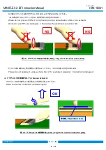
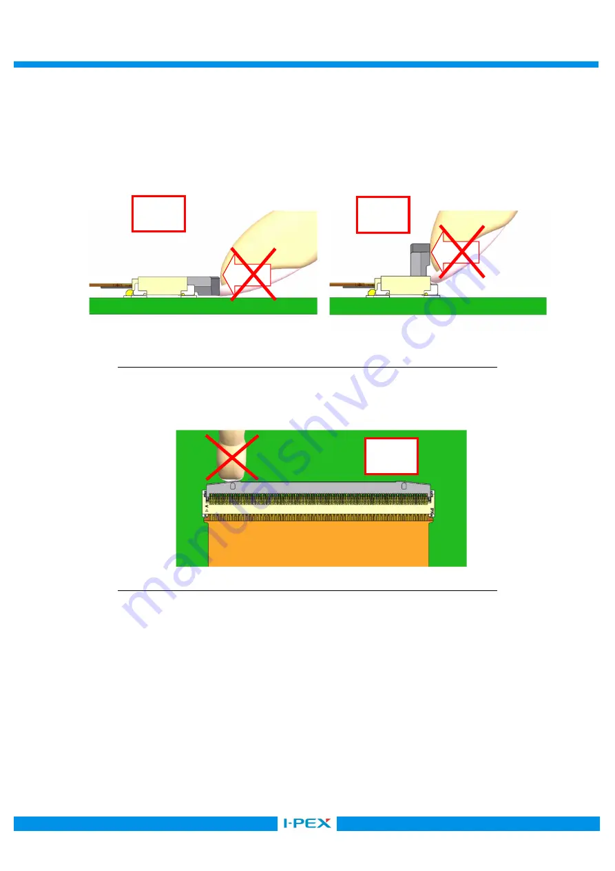
・ピンセット等の鋭利な工具を使用して操作しないで下さい。 コネクタを傷つける恐れがあります。
Please do not operate it using a sharp tool. (For example, tweezers) Connector is damaged.
NG
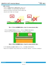
NG
NG


