background image


MINIFLEX 2-BF Instruction Manual


Document No. 

HIM-16031


3

  / 

12


Confidential C                                                                   

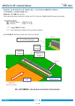
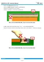
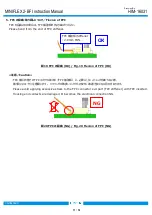
1.  コネクタ実装状態(FPC 挿入前)/Connector mounting state (Before FPC insertion) 

アクチュエータ開放状態での納入となりますので、FPC を挿入する前にアクチュエータを操作する必要はありません。 
Connectors are delivered with actuator open. There is no need to operate the actuator before FPC insertion. 


図 2.  コネクタ実装状態  / Fig.2 Connector mounting state 
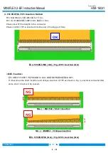


≪注意/Caution≫ 

・FPC 未挿入状態においてアクチュエータをロック(空ロック)しても、接圧に大きな影響はなく、信頼性を損なう事は御座いません。 

但し、接点間の寸法が狭くなり FPC を挿入する際に挿入力が高くなる可能性がありますので、極力避けて 
頂きますよう、お願い申し上げます。 
Even if the actuator is locked without FPC (FPC is not inserted), there is no remarkable affect to the contact   
pressure and the reliability will not be damaged. 
However, there is the possibility that the insertion force rises in inserting FPC, because the gap of contacts   
became narrowed.    Therefore, please avoid locking the actuator without FPC as much as possible. 


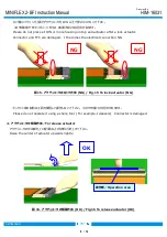
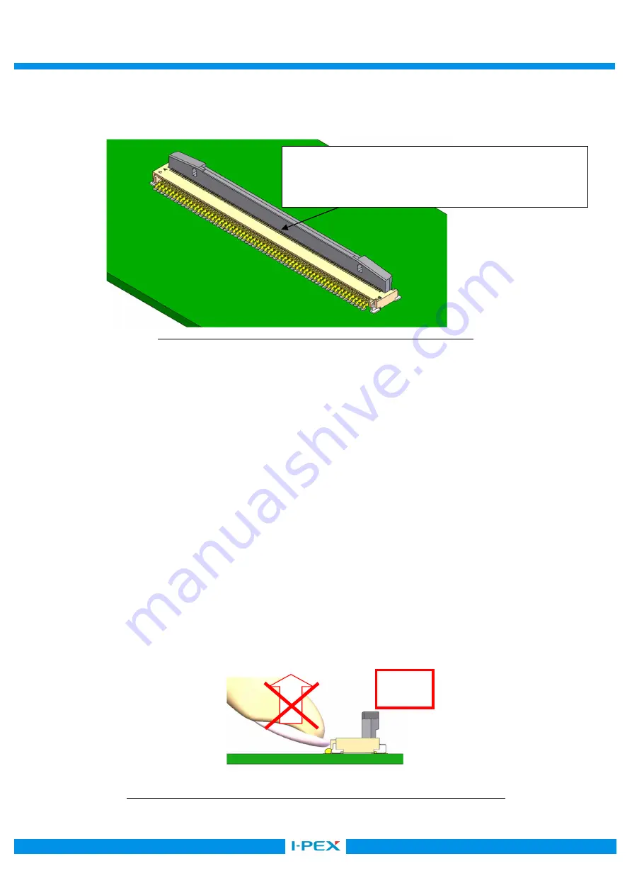
・補修などで手半田を行う場合は、コンタクトテールに触れないように御願い致します。 

        また、過度の半田及びフラックスは供給しないで下さい。 
        In case of the manual mounting do not to touch contact tail. 
        Please do not use excessive amount of solder and flux compounds. 


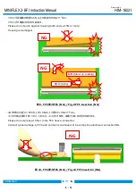
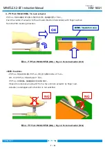
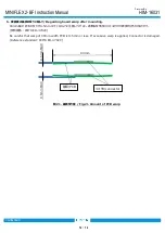
・ハウジング間口部に過度な負荷を与えないでください。ハウジングが破損する恐れがあります。 
  Please avoid applying excessive stress to exit part of Housing.    Housing is damaged. 


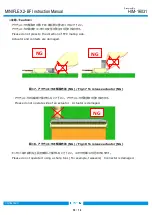
図 3.  コネクタ実装状態  (NG) / Fig.3 Connector mounting state (NG)


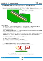
エンボス納入時よりアクチュエータは開放状態です。 
The actuator is open when delivered in the embossed 
tape packaging. 

NG 

Summary of Contents for 20617-080E-01

Page 1: ...Inc QKE DFFDE09 03 REV 8 MINIFLEX 2 BF 0 2mm pitch FPC Conn Part No 20617 E 01 Instruction Manual 1 S19620 October 2 2019 R Morita T Masunaga H Ikari 0 S17016 January 12 2017 Y Sasa T Masunaga H Ikari...

Page 2: ...handle our FPC connector MINIFLEX2 BF properly and safely Connector Product Name MINIFLEX 2 BF Part No 20617 E 01 part shows the number of the connector position Names of each part of the connector 1...

Page 3: ...to the contact pressure and the reliability will not be damaged However there is the possibility that the insertion force rises in inserting FPC because the gap of contacts became narrowed Therefore p...

Page 4: ...connector Please confirm FPC is inserted into the end of mating part fully 4 FPC OK Fig 4 FPC insertion OK Caution 5 FPC If it becomes the short insertion and oblique insertion of FPC as shown in Fig...

Page 5: ...check of FPC insertion becomes easy by preparing the wing in FPC and preparing the silk print in board 6 FPC Fig 6 The check of FPC insertion Reference 7 FPC OK Fig 7 FPC insertion OK NG Short inserti...

Page 6: ...housing both ends at 5N or more Housing is damaged 9 FPC NG Fig 9 FPC insertion NG FPC 5N FPC Please do not press at 5N or more FPC near a connector Contact gives damage to FPC and contact is damaged...

Page 7: ...ator to the arrowed direction horizontally with finger cushion from the FPC inserting direction 11 OK Fig 11 To lock actuator OK Caution Please do not press an actuator from a top and lock actuator by...

Page 8: ...ntial C Please do not operate side of an actuator Actuator is damaged or it becomes imperfect lock 13 NG Fig 13 To lock actuator NG Please do not press contact on top by finger nail etc after a lock a...

Page 9: ...tor after a lock actuator Connector and FPC are damaged It becomes the electrical connection NG 15 NG Fig 15 To lock actuator NG Please do not operate it using a sharp tool For example tweezers Connec...

Page 10: ...ress to the direction of FPC mating side Actuator and contacts are damaged 17 NG Fig 17 To release actuator NG Please do not operate side of an actuator Actuator is damaged 18 NG Fig 18 To release act...

Page 11: ...the end of FPC stiffener 19 FPC OK Fig 19 Flexion of FPC OK Caution FPC FPC FPC Please avoid applying excessive stress to the FPC connector exit part FPC stiffener with FPC inserted Housing and conta...

Page 12: ...6 Regarding board warp after mounting 90mm PCB 0 5mm JEITA ED 4702C Be careful that warp of 90mm width PCB is 0 5mm or less If excessive warp is applied Connector is damaged Reference standard JEITA E...

Reviews: