background image


CABLINE-CA Assembly Manual


Document No. 

ASM-09005


13

  / 

14


Confidential C                                                                   

SHELL-A,B

GND BAR

を半田コテにて全箇所半田付けする。  (

Fig.8,9

◆部)


半田の高さ(半田量)の限度は

Fig.12

参照。


半田コテの条件は、

9

頁参照。


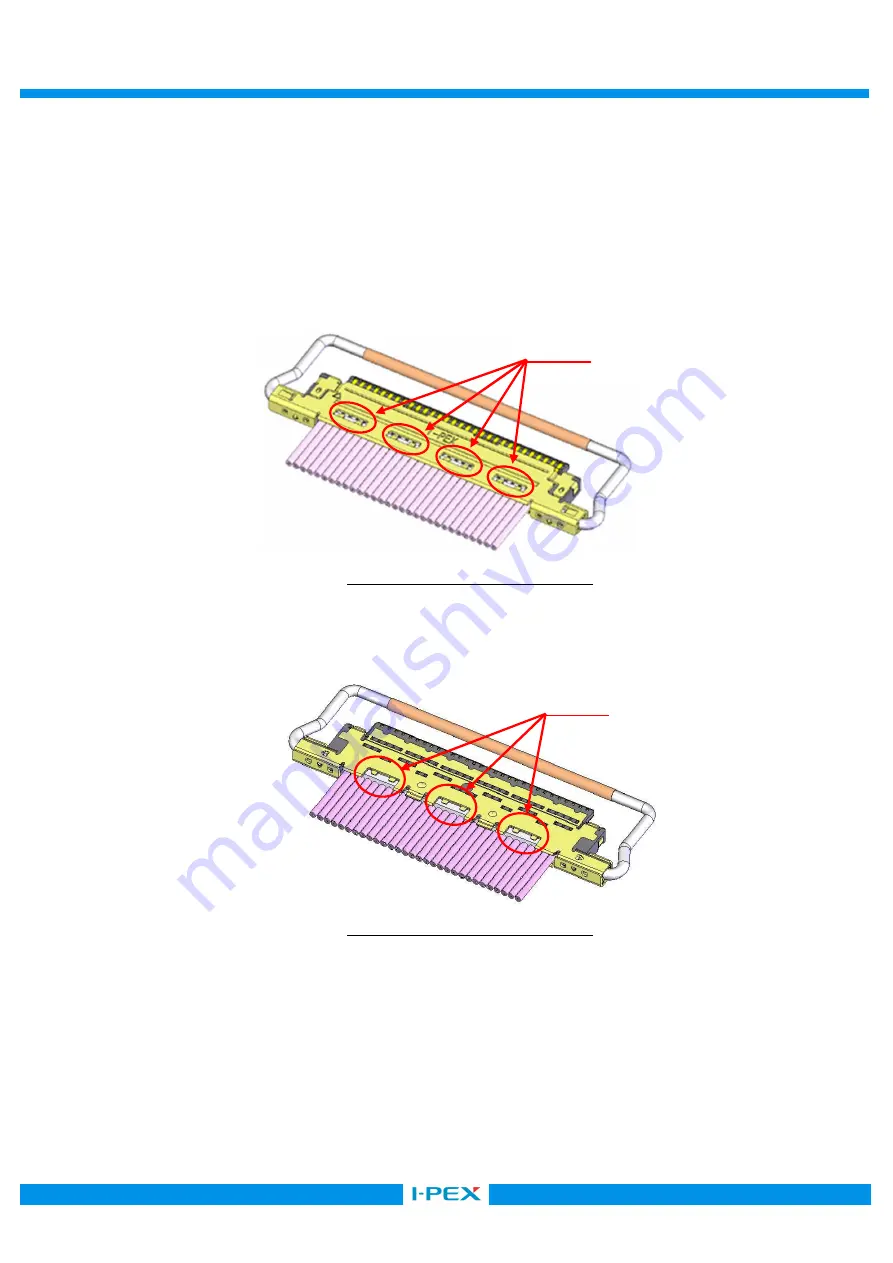
SHELL-A, B and GND BAR are soldered with the soldering iron at all designated points. (Fig.8,9

point) 

          Refer to Fig.12 for a limit of the solder height.   

For conditions of Soldering iron refer to sheet 9. 


Fig.8 Soldering of SHELL-A and GND BAR 


Fig.9 Soldering of SHELL-B and GND BAR 


Point 

Point 

Summary of Contents for 20633-210T-01S

Page 1: ...Document No ASM 09005 CABLINE CA PLUG Part No 20633 Assembly Manual 8 S18410 June 29 2018 M Nakamura Y Shimada 7 S16129 March 4 2016 Y Sasa T Kurachi J Tateishi 6 S15089 February 26 2015 K Baba E Kawa...

Page 2: ...ation Pulse heater Heater chip 10P 12P 20P 30P 40P 50P 60P Thickness 0 5 0 0 05 0 5 0 0 05 0 5 0 0 05 0 5 0 0 05 0 5 0 0 05 0 5 0 0 05 0 5 0 0 05 Width 4 2 0 0 03 5 0 0 0 03 8 2 0 0 03 12 2 0 0 03 16...

Page 3: ...temp 300 320 rise time 0 5sec holding time 3 0sec Heater tip Pressure 5 10N This pulse heat condition was evaluated and confirmed by our pulse heat jig and instruments The most optimum condition may c...

Page 4: ...nt No ASM 09005 4 14 Confidential C 5 Work procedures 5 1 Soldering of center conductor The cables have to be fabricated as shown below in advance of soldering Pos A 10P 3 60 12P 4 40 20P 7 60 30P 11...

Page 5: ...CABLINE CAAssembly Manual Document No ASM 09005 5 14 Confidential C...

Page 6: ...CABLINE CAAssembly Manual Document No ASM 09005 6 14 Confidential C...

Page 7: ...please confirm all contacts were applied flux Photo 1 After applying flux Photo 2 Please do not apply flux too much like Photo 2 It can cause flux splash or leak to the mating area Photo 2 Extra flux...

Page 8: ...locate solder bar at center of connector HSG ASS Y Fig 1 Set of solder bar Set the cable SHELL Fig 3 0 2MAX Setting discrete cable is to protect 0 2MAX as Fig 3 There is danger that Center Conductor...

Page 9: ...WG 40 PLUG HSG ASS Y SHELL Fig 4 JIG Caution The SHELL bottom side of PLUG HSG ASS Y has convex shape at the points shown in Fig 4 so please make escape shape on the receiving jig of the pulse heater...

Page 10: ...soldering 5 2 SHELL A Cautions in treating SHELL A SHELL A SHELL A SHELL A is delivered in the reel with a carrier The following is the method to cut SHELL A from Carrier Cut Line Cut carrier on the...

Page 11: ...photo below to cut off by force Red arrow direction burrs and transformation can be caused 5 3 PULL BAR Assembly of PULL BAR Fig 5 PULL BAR HOUSING ASS Y PULL BAR is assembled to HOUSING ASS Y Fig 5...

Page 12: ...ELL A Fig 6 SHELL A HOUSING ASS Y SHELL A is assembled from the upper side of HOUSING ASS Y Fig 6 Assembly of SHELL A SHELL A SHELL Fig 7 Confirms whether SHELL A is assembled properly Whether SHELL l...

Page 13: ...Fig 12 9 SHELL A B and GND BAR are soldered with the soldering iron at all designated points Fig 8 9 point Refer to Fig 12 for a limit of the solder height For conditions of Soldering iron refer to sh...

Page 14: ...ldered with the soldering iron at all designated points Fig 10 point Conditions of Soldering iron refer to sheet 9 Fig 10 Soldering of SHELL A and SHELL B 5 5 Cable fixation LOCTITE 352 Fix the cable...

Reviews: