background image


CABLINE-UY PLUG Assembly Manual


Document No. 

ASM-18002


11

  / 

22


Confidential C                                                                   

45

°


45

°


6.SHELL A

圧着手順(

SHELL A crimping procedure


6-1. SHELL A

取扱注意事項 

(Cautions in treating SHELL A) 

SHELL A

はキャリア付きリール状態にて納品されます。

SHELL A

をキャリアから折り取る手順を明記します。


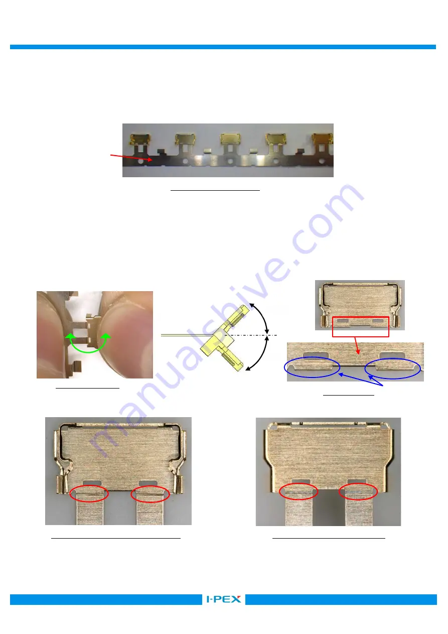
SHELL A is delivered in the reel with a carrier. The following is the method to cut SHELL A from Carrier. 


SHELL A

の中心部を持ち、

±45°

の範囲で

1

往復させてノッチ部から切り離す。もし、切り離れない場合は、この往復動作を繰り返し

て切り離す。切り離し後はノッチ折り取り部にバリ発生なきことを確認してください。バリがあるまま圧着を行うとケーブルを傷つける恐れ
があるので、バリがある場合はカッターなどで取り除いてください(

Photo.10


Hold the center of SHELL A and cut it off from Notch by 

±

45 deg of reciprocating work. 

When it does not be cut, try again this reciprocating work. After separated, check there is no burr around the cut part.

Photo.10


PLUG SHELL A 

ノッチ部状態

  (Details of Notch)   


Photo. 8 SHELL A from Carrier. 

Photo. 9 Cut condition 

Photo.10 After cut 

Without burrs 

Photo.11 HSG ASS’Y

挿入側 

(Mating side) 

Photo.12 

背面側

  (Back surface side) 

Carrier 

Summary of Contents for 20857-005T-01

Page 1: ...art No 20857 Assembly Manual 4 S20228 April 21 2020 Y Fukumoto T Yamauchi 3 S20219 April 15 2020 H Takao J Tonai Y Hashimoto 2 S20070 February 20 2020 R Takahashi Y Fukumoto T Yamauchi 1 S20016 Januar...

Page 2: ...1 05 5P 10 10P 3 Fixtures 3 1 Components and Instruments used in the condition confirmation Pulse heater Heater chip Unit mm Recommended solder bar Resin free solder is used Unit mm Positions 5P 10P S...

Page 3: ...2nd heat temp 240 rise time 0 5sec holding time 1 5sec Heater tip Pressure 0N This pulse heat condition was evaluated and confirmed by our pulse heat jig and instruments The most optimum condition ma...

Page 4: ...PLUG Assembly Manual Document No ASM 18002 4 22 Confidential C 5 Work procedures 5 1 Soldering of center conductor The cables have to be fabricated as shown below in advance of soldering C 5Pin 1 4 1...

Page 5: ...CABLINE UY PLUG Assembly Manual Document No ASM 18002 5 22 Confidential C C 5Pin 1 4 10Pin 3 15...

Page 6: ...s were applied flux Photo 1 After applying flux Photo 2 Please do not apply flux too much as shown in Photo 2 It may cause flux splash or leak to the mating area Photo 2 Extra flux If flux applied too...

Page 7: ...cable Caution Pad Pad Ground Bar GND BAR Center conductor must be fit on Pad The tip of cable should be exceed the center of pad Ground Bar should be contained in housing part Solder Bar Cable settin...

Page 8: ...18002 8 22 Confidential C 5 1 If the length of center conductor is not the length indicated in 5 1 pulse heat may not be performed normally Pad The tip of center conductor does not reach the center of...

Page 9: ...r bridge is appeared between the terminal try heating again with pulse heater only one time Do not rework more than two times to avoid causing damage on product If the bridge isn t repaired use the so...

Page 10: ...al C Discrete cable UV For Discrete cable specifications it is recommended to apply UV resin to the soldered part Fig 4 Bonding OK NG Photo 6 UV Apply resin appearance OK Photo 7 UV Apply resin appear...

Page 11: ...hod to cut SHELLA from Carrier SHELL A 45 1 Photo 10 Hold the center of SHELLA and cut it off from Notch by 45 deg of reciprocating work When it does not be cut try again this reciprocating work After...

Page 12: ...sembly Manual Document No ASM 18002 12 22 Confidential C Photo 13 Caution By pulling like the photo below to cut off by force Red arrow direction burrs and transformation can be caused Photo 13 Cut by...

Page 13: ...6 1 SHELLA JIG JIG Photo 12 Set the SHELLA that cut it off in 6 1 on receive JIG of crimping Jig as shown in photo15 Back surface side Refer to photo 12 shall be below and carrier cut side shall be f...

Page 14: ...ial C Sheet 8 HSG ASS Y SHELLA photo16 Assemble the HSG ASS Y to SHELLA so that crimping side shall be below and cable shall be front Photo 16 Fig 5 Setting HSG ASS Y HSG ASS Y SHELLA Insert the HSG A...

Page 15: ...g NG HSG ASS Y SHELL A HSG ASS Y is set in the slit part of SHELL A HSG ASS Y SHELL A HSG photo 18 HSG ASS Y is mounting on the SHELL A Be caution if crimp in this condition HSG will be broken Refer t...

Page 16: ...sed coaxial cable Therefore non specified connectors and cables are not allowed Failure to do so may damage the jig With the exception of the specified replacement area loosen or removing bolts are pr...

Page 17: ...ct is properly wired and crimped Photo 21 crimping appearance OK 7 1 SHELLA crimping appearance OK NG OK NG Photo 22 crimping appearance OK Photo 23 crimping appearance NG SHELLA HSG ASS Y HSG ASS Y s...

Page 18: ...Receptacle If the crimp height is not appropriate it may not be able to mate normally with Receptacle Crimping height OK Crimping height NG Crimp height 0 69 0 73mm Photo 26 Dimension of crimping hei...

Page 19: ...GND BAR Fig 8 8 SHELLA and GND BAR are soldered with the soldering iron at designated points Fig 8 point For conditions of Soldering iron refer to sheet 8 Fig 8 Soldering of SHELLA and GND BAR Fig 9 S...

Page 20: ...ND BAR OK NG Soldering of SHELLA and GND BAR appearance OK NG OK NG Photo 30 Soldering of SHELLA and GND BAR appearance OK Photo 31 Soldering of SHELLA and GND BAR appearance NG Photo 32 Soldering of...

Page 21: ...E 352 Fig 10 Bonding Bonding Bonding shall not exceed the limit criteria Immediately after application of Bonding expose and solidify If left unattended the adhesive will penetrate into the connector...

Page 22: ...UG Assembly Manual Document No ASM 18002 22 22 Confidential C 10 Finished product appearance example MICRO COAX CABLE DISCRETE CABLE Photo 38 Finished product appearance OK Photo 39 Finished product a...

Reviews: