


CABLINE-UY PLUG Assembly Manual
Document No.
ASM-18002
16
/
22
Confidential C
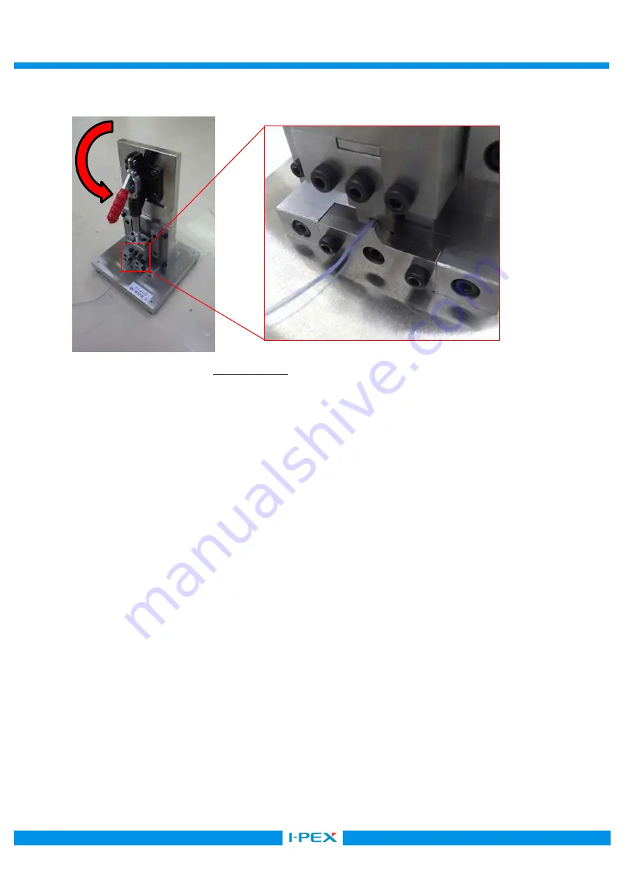
③圧着機のレバーをおろし、圧着する
(photo20)
Pull down the lever of crimping machine and crimp the product.
④レバーを上げてハーネスを取り出す。
(Up the lever and pull out the product)
6-4.
圧着機取り扱い上の注意及び保守
/Cautions and Maintenances
●本治具は
I
-
PEX
端子
CABLINE-UY(P/N:3568-0**1)
と端子専用加工を施されたケーブルとをハーネスする為の圧着機です。
従って他の端子及び指定外
(
適合しない
)
同軸線にてハーネスを行いますと治具の損傷を招く恐れがありますので、
そのような指定以外の端子の使用は行わないでください。
●むやみに組替え部分以外のボルトを緩めたり、外したりしないで下さい。又、部品改造したりしますと治具の
設定に狂いが生じ組立て製品の品質に影響を与えますので絶対に行わないで下さい。
●治具のお手入れは、定期的に製品に関わる部分に付着しているケーブル切り屑等をブラシ、エアー等にて
必ず清掃して下さい。又、摺動部にはミシン油か市販の防錆油を塗布してから保管して下さい。
●
This Semi Auto machine is a jig for harnessing I-PEX CABLINE-UY(P/N:3568-0**1) to a specially processed coaxial cable. Therefore, non-
specified connectors and cables are not allowed. Failure to do so may damage the jig.
●
With the exception of the specified replacement area, loosen or removing bolts are prohibited. Modifying is prohibited to avoid the defect of
the jig. Failure to do so may affect the quality of the product.
●
For the jig maintenance, use brushes and air pressure regularly to remove cable chips and dusts on the jig. Apply sewing machine oil or
the rust preventing oil (store-bought) to the sliding surfaces regularly.
Photo.20 Crimping


