CABLINE-CAF Assembly Manual
Document No.
ASM-18005
8
/
10
Confidential C
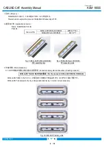
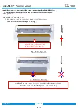
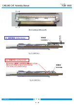
3-3. FPC
半田付け
(FPC soldering)
FPC
に半田付け部を設け、上下面共に半田付けを必ず実施してください。
(図
9
の FPC は参考の
FPC
です。)
Apply metallic material on top and bottom surfaces of the FPC to install soldering portion on the FPC.
(The FPC shown in Fig. 9 is a reference)
Fig.9 FPC which can be soldered
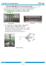
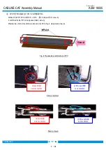
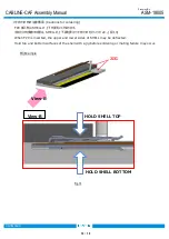
①
SHELL
と
FPC
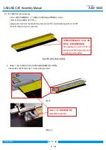
を半田付けする
(
半田付け量の詳細は図
11
参照
)
。
Solder SHELL and FPC(See Fig.11 for the soldering amount.).
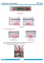
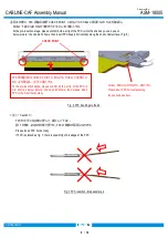
半田付け可能なように
FPC
を一部
開口し、半田付け部を追加
The opening of a part of FPC is
carried out so that it can solder, and
a soldering part is added.
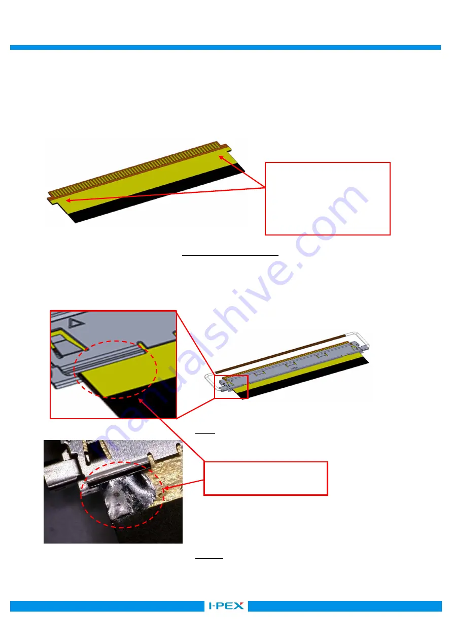
SHELL
と
FPC
を半田付けする
Solder SHELL and FPC.
Fig. 10
Photo. 10


