
CABLINE
®
-VS IIF Instruction Manual
Document No.
HIM-17039
2
/
11
Confidential C
弊社、CABLINE-VS IIF CONN.の取り扱いに際して、本コネクタを安全に御使用頂くことを目的とし、コネクタの挿入・抜去の
手順及び注意点を記述致します。
This manual provides the mating & un-mating methods and cautions to handle CABLINE-VS IIF
connector properly.
【対象コネクタ名称・型番】 / Connector Name, Part number
◆プラグコネクタ (Plug connector)
名称 / Product Name
: CABLINE-VS IIF SHELL ASS’Y
型番 / Part No.
: 20862-0**T-01
◆基板側コネクタ (Receptacle connector)
名称 / Product Name
: CABLINE-VS II RECEPTACLE
型番 / Part No.
: 20849-0**E-0
※
“**”には各芯数番号が入ります。
(“**” part shows the number of the connector position).
“※”はバリエーションになります。詳細は図面を参照願います。
(‘‘※’’ part shows the variation.
Please refer to a drawing for the details.)
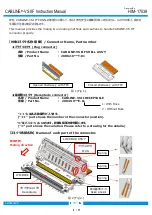
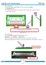
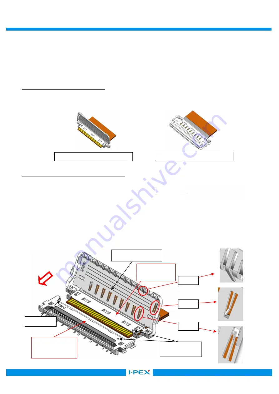
【コネクタ各部名称】 Names of each part of the connector.
リセプタクルコネクタ
Receptacle
嵌合基準マーク
Datum pin mark
嵌合方向
Mating direction
LOCK BAR ASS’Y
図 1 (Fig 1.)
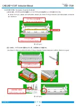
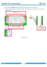
1: With Boss
2:Without Boss
I-PEX MARK
プラグコネクタ
PLUG
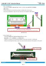
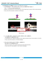
図 2 (Fig 2.)
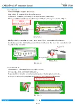
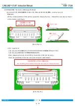
Opened shell ass’y with FPC
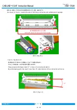
Closed shell ass’y with FPC
Spring
Spring
Spring


