
CABLINE
®
-VS IIF Instruction Manual
Document No.
HIM-17039
4
/
11
Confidential C
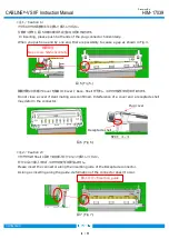
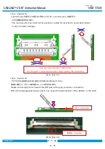
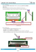
<注 1/Caution 1>
プラグコネクタの両側を水平に押して挿入してください。
片側ずつ押すと、図 5 の様に嵌合不完全になる恐れがあります。
In inserting, please push both ends of the plug connector horizontally.
When you push one end by one end, there is possibility to cause a gap as shown in Fig.3.
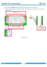
隙間が開いた状態で Cover を閉めると Cover と Rece. Shell が干渉し、コネクタが変形する恐れがあります。
Do not close a cover if slant mating was confirmed. Interference of a cover and a receptacle shell
may deform the connector.
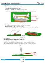
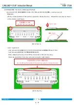
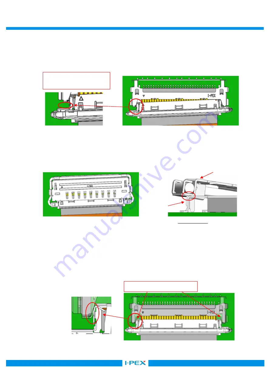
<注 2/Caution 2>
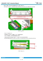
リセプタクルの Shell に設けてある挿入ガイドに沿って挿入してください。
ガイドに沿って挿入すれば、コネクタの変形は発生しません。
Please insert the connector along the insertion guide of the Receptacle connector.
As long as inserting along the guide, deformation of the connector doesn't occur.
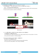
SECT. X-X
Plug cover
Receptacle shell
隙間発生
Gap occurs NG horizontally
図 5 (Fig 5.)
図 6 (Fig 6.)
挿入ガイド/Insertion guide
図 7 (Fig 7.)


