background image


EVAFLEX 5-HD Instruction Manual


Document No. 

HIM-19004


3

  / 

10


Confidential C                                                                   

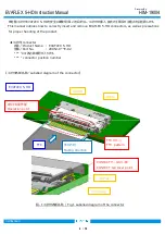
【  FFC 挿入手順  /FFC Insertion Method  】 


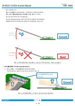
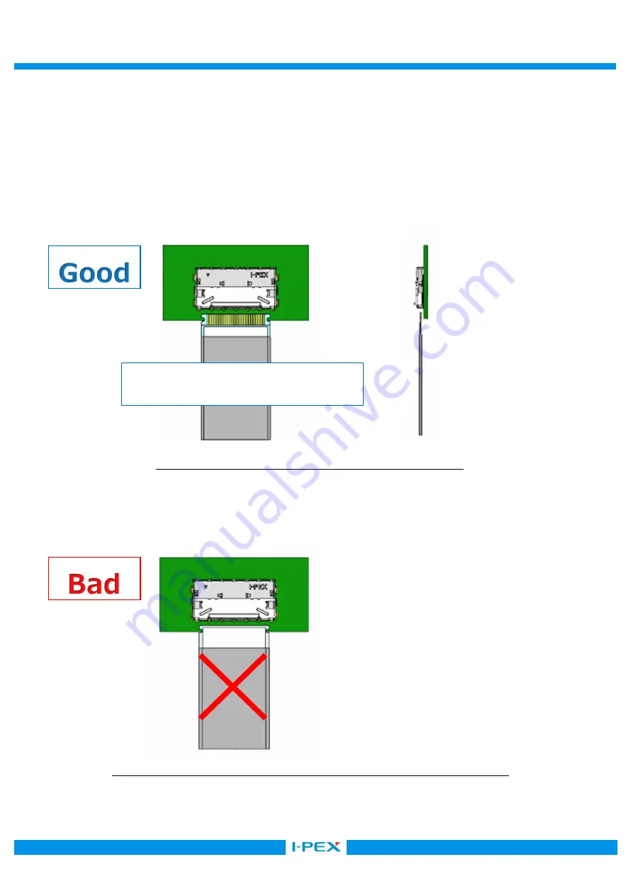
図 2-1 の様に、FFC のパターンを上に向けて挿入間口に対し水平にセットする。 

※本製品は上接点タイプのみですので、FFC のパターンは上を向けた状態でセットしてください。 

また FFC 挿入手順で COVER の操作は不要です。


    Place FFC pattern upward and set it horizontally against PCB as shown in Fig.2-1. 


※EVAFLEX 5-HD is a top contacting type connector. Make sure that FFC pattern is facing upward. 

Keep cover closed while inserting FFC.
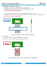
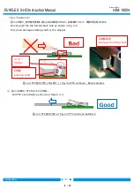


<注 1/Caution 1> 

        図 2-2 のように FFC のパターンを下に向けた状態での挿入はしないでください。 

Do not insert while FFC pattern is facing downward. (Fig.2-2) 


図. 2-1  FFC 挿入方法  1 / Fig.2-1 FFC inserting method 1 

図. 2-2 FFC 挿入方法  ( NG 例  1 ) / Fig.2-2 FFC insertion – Bad example 1 

FFC のパターンを上に向けてセットする 

FFC pattern shall face upward 

Summary of Contents for 20952-024E-02

Page 1: ...tial C I PEX Inc QKE DFFDE09 03 REV 8 EVAFLEX 5 HD Part No 20952 0 E 02 Instruction Manual 1 S20009 January 9 2020 H Kaneko M Muro H Ikari 0 S19053 August 23 2019 H Kaneko M Muro H Ikari Rev ECN Date...

Page 2: ...nnectors as well as precautions for proper handling of the product connector Product Name EVAFLEX 5 HD Part No 20952 0 E 02 connector position number Labelled diagram of the connector Mating direction...

Page 3: ...ly against PCB as shown in Fig 2 1 EVAFLEX 5 HD is a top contacting type connector Make sure that FFC pattern is facing upward Keep cover closed while inserting FFC 1 Caution 1 2 2 FFC Do not insert w...

Page 4: ...aution 2 2 4 6 0 FFC shall not exceed 6 degrees toward the connector Do not apply excessive load until FFC is aligned vertically Slightly insert FFC before pushing it completely Fig 2 4 FFC Insert FFC...

Page 5: ...Do not apply excessive load until FFC is aligned horizontally Slightly insert FFC before pushing it completely Fig 2 5 FFC FFC Removal Method 3 1 Pull the tab to open the cover as shown in fig 3 1 3...

Page 6: ...Do not push the tab toward back side as shown in fig 3 2 This could damage rotating shaft or the stopper 3 3 FFC Pull FFC horizontally as shown in Figure 3 3 Stopper Rotating shaft 3 2 FFC NG 1 Fig 3...

Page 7: ...ion 5 3 4 FFC FFC FFC 3 1 Straightly remove FFC from the connector Fig 3 4 Do not tilt FFC or it may damage FFC or FFC pattern Photo 3 1 3 1 FFC Comparing removed FFC pattern a Straightly removed b Ob...

Page 8: ...COVER Close cover after FFC is removed completely as shown in Figure 3 3 3 a b Photo 3 3 Comparing proper and improper removal of the FFC FFC Lock FFC FFC interferes with the lock during insertion mak...

Page 9: ...cessive force to the cover surface Fig 3 6 It may damage connector Cautions in handling the connector FFC FFC 4 1 FFC Do not pull FFC vertically toward PCB as this may damage FFC or the connector Phot...

Page 10: ...10 Confidential C FFC FFC FFC Do not apply excessive force to the connector and FFC or they may be damaged FFC FFC Do not pull around FFC that will apply continuous stress to the connector as this may...

Reviews: