EVAFLEX 5-HD Instruction Manual
Document No.
HIM-19004
8
/
10
Confidential C
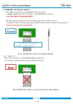
<注 6/Caution 6>
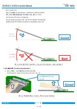
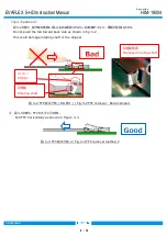
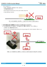
COVER が閉じている状態で FFC の抜去(強制抜去)はしないで下さい。( 写真 3-2 )
FFC 及びコネクタを破損させる原因となります。( 写真 3-3 )
Do not pull FFC while cover is closed. [Photo. 3-2]
It may damage FFC or connector. [Photo. 3-3]
④
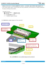
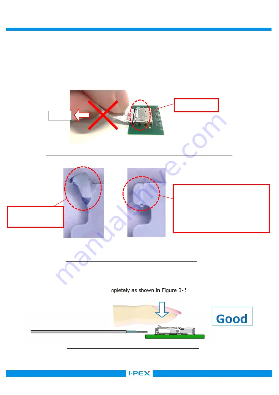
図 3-5 の様に、FFC 抜去後に COVER を閉じる。
Close cover after FFC is removed completely as shown in Figure 3-5.
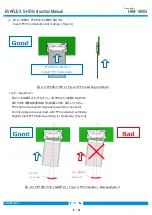
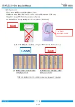
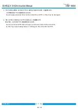
写真.3-3. (a)強制抜去を行った場合 (b)通常抜去を行った場合
Photo.3-3 Comparing proper and improper removal of the FFC
FFC は挿入時に Lock と干渉するため、
FFC 耳に摺動痕があります。
FFC interferes with the lock during
insertion, making slide marks on the
FFC ear.
FFC 耳変形
Damaged FFC ear
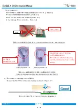
写真. 3-2 FFC 抜去方法 ( NG 例 3 ) / Photo.3-2 FFC removal – Bad example 3
図. 3-5 FFC 抜去方法 3 / Fig.3-5 FFC removal method 3
Cover closed
(a) Improperly removed FFC
(b) Properly removed FFC
PULL


