background image


CABLINE-CX II PLUG With Cover Assembly Manual


Document No. 

ASM-17008


3

  / 

16


Confidential C                                                                   

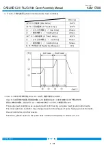
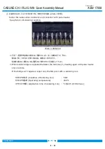
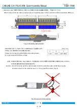
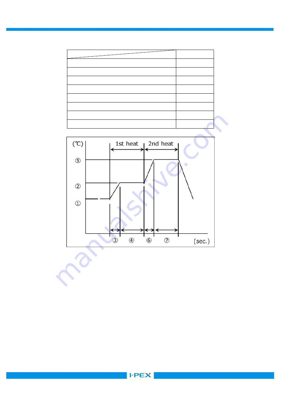
4.  パルスヒート条件[推奨] (Recommended pulse heat condition) 


Micro-Coax 

①アイドリング温度  (Idle temp.) 

150℃ 

②1

st

ヒート設定温度  (1

st

 heat temp.) 

220℃ 

③    〃  立ち上がり時間  (  〃  rise time) 

0.5sec. 

④    〃  維持時間  (  〃  holding time) 

2.0sec. 

⑤2

nd

ヒート設定温度  (2

nd 

heat  temp.) 

320℃ 

⑥    〃  立ち上がり時間  (  〃  rise time) 

0.5sec. 

⑦    〃  維持時間  (  〃  holding time) 

5.0sec. 

ヒーターチップ加圧力(Heater tip Pressure) 

11N 


※パルスヒート条件の評価は弊社のパルスヒート冶具、装置で確認しております。 

パルスヒート冶具形状や装置、環境等の違いにより、最適なパルスヒート条件は変わることが予想されます。 
貴社で御使用の際は、充分なパルスヒート条件の検討を行っていただくよう御願い致します。 
This pulse heat condition was evaluated and confirmed by our pulse heat jig and instruments. 
The most optimum condition may change based on the shapes of pulse heat jig and instruments,   
the environments, or other reason. 
Therefore, please examine the pulse heat condition adequately in advance of use. 

Summary of Contents for 20977-040T-01

Page 1: ...BLINE CX II PLUG With Cover Part No 20977 Assembly Manual 2 S19503 September 4 2019 S Yamaguchi T Kurachi H Ikari 1 S17876 November 28 2017 R Hoshino T Yayoshi M Takemoto 0 S17752 October 13 2017 R Ho...

Page 2: ...COVER CABLE ASS Y 20977 040T 01 Discrete P N HOUSING ASS Y 20974 040T 01 LOCK BAR ASS Y 20975 040T 01 SHELL A 3655 0401 3 Fixtures 3 1 Components and Instruments used in the condition confirmation Pu...

Page 3: ...g time 2 0sec 2nd 2nd heat temp 320 rise time 0 5sec holding time 5 0sec Heater tip Pressure 11N This pulse heat condition was evaluated and confirmed by our pulse heat jig and instruments The most op...

Page 4: ...nt No ASM 17008 4 16 Confidential C 5 Work procedures 5 1 Soldering of center conductor The cables have to be fabricated as shown below in advance of soldering Micro coax cable Unit mm Micro coax cabl...

Page 5: ...CABLINE CX II PLUG With Cover Assembly Manual Document No ASM 17008 5 16 Confidential C Discrete cable Unit mm...

Page 6: ...ase confirm all contacts were applied flux Fig 1 After applying flux Photo 1 After applying flux Photo 2 Please do not apply flux too much like Photo 2 It can cause flux splash or leak to the mating a...

Page 7: ...and locate solder bar at center of soldering point Fig 2 Set solder bar Set the cable Fig 3 Setting Cable MCX Discrete cable Jacket When using a discrete cable set it so that the end of the jacket an...

Page 8: ...lse heater See photo 3 of soldering condition Photo 3 AWG 44 1 NG When solder bridge is appeared between the terminal try heating again with pulse heater only one time If the bridge isn t repaired rep...

Page 9: ...ore assemble SHELL A Fig 6 Caution Do not forcedly pull the cable toward red arrow direction after soldering or apply excessive load on the soldered area or it may peel the solder Fig 6 Fig 6 Cause of...

Page 10: ...below picture green line by a scissors for metal SHELL A 45 1 Photo 7 Hold the center of Plug shell A and cut it off from Notch by 45 degrees of reciprocating work When it does not be cut try again th...

Page 11: ...photo below to cut off by force Red arrow direction burrs and transformation can be caused 5 3 LOCK BAR ASS Y Assembly of LOCK BAR ASS Y Fig 7 LOCK BAR ASS Y HOUSING ASS Y LOCK BAR ASS Y is assembled...

Page 12: ...Fig 8 LOCK BAR ASS Y 120 HOUSING ASS Y SHELL A Fig 9 LOCK BAR ASS Y is tilted to the cable side 120 degrees Place the SHELL A on the upper surface of the HOUSING ASS Y and push only the red shaded are...

Page 13: ...anual Document No ASM 17008 13 16 Confidential C point Fig 10 Check point Fig 10 from the front of connector as shown below Fig 10 Confirm whether SHELL A Check point Y OK NG Red line below blue line...

Page 14: ...Assembly Manual Document No ASM 17008 14 16 Confidential C points Confirm whether Fig 11 points is assembled properly and SHELL A locks properly Fig 11 Assembly of SHELL A LOCK BAR ASS Y Closed LOCK...

Page 15: ...ignated points Fig 12 13 point Conditions of Soldering iron refer to sheet 8 Fig 12 Soldering of Shell A and Ground Bar Fig 13 Soldering of Shell B and Ground bar Shell A and Shell B When soldering do...

Page 16: ...er Assembly Manual Document No ASM 17008 16 16 Confidential C 5 5 Cable fixation SHELL LOCTITE 352 Fix the cable and SHELL with the bond Recommended Bond LOCTITE 352 Fig 14 Bonding Fig 15 Soldering Bo...

Reviews: