
CABLINE-CX II PLUG With Cover Assembly Manual
Document No.
ASM-17008
9
/
16
Confidential C
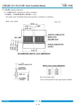
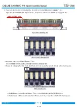
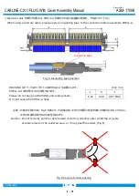
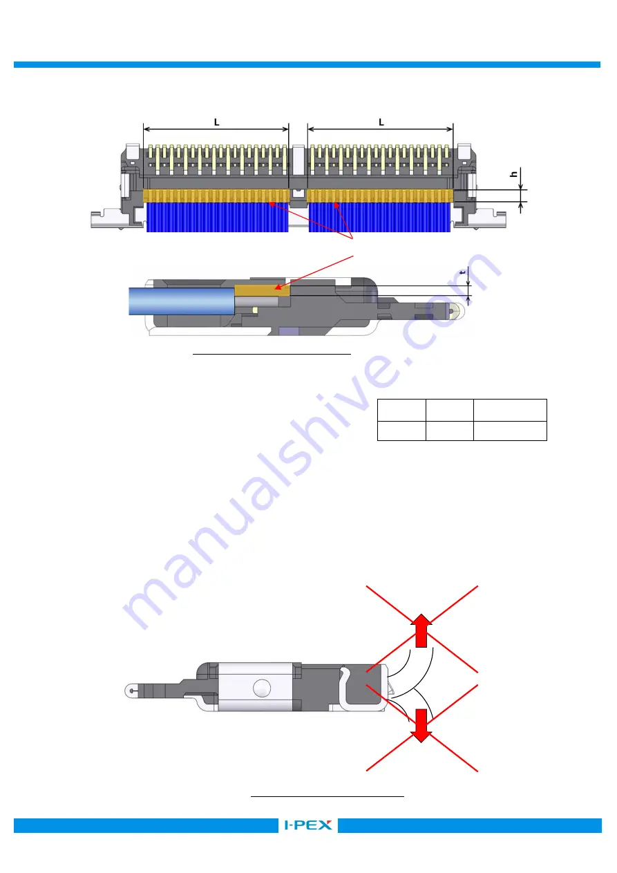
※Discrete cable を使用する場合は、SHELL-A を取り付ける前に結線部に絶縁テープを貼りつけて下さい。
When using a discrete cable, please apply an insulating tape to the connection before assemble SHELL-A.
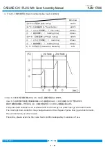
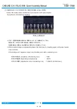
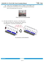
注意:芯線の半田付け後、Fig.6 の様にケーブルを煽る等、半田付け箇所に負荷が加わる作業は行わないでください。
半田付け箇所が剥がれる可能性があります。
Caution: Do not forcedly pull the cable toward red arrow direction after soldering or apply
excessive load on the soldered area, or it may peel the solder. (Fig.6)
Fig.6 Cause of solder peeling
L
h
t
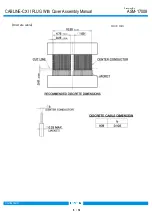
5.10
0.40
0.07 MAX.
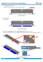
HOUSING 及びケーブルのジャケットには掛からないようにお願いします。
SHELL-A の浮きが発生する可能性があります。
Please do not hang on HOUSING and cable jackets.
It might cause the SHELL-A float.
Unit: mm
Fig. 5 Insulating tape position
Insulating tape