background image


CABLINE

®

-CA IIF Instruction Manual


Document No. 

HIM-17029


10

  / 

11


Confidential C                                                                   


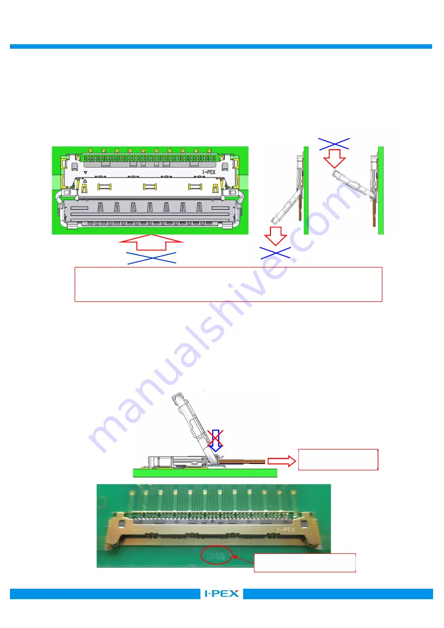
        <注 11/Caution 11> 
            Lock bar ass’y を操作しての抜去は行わないでください。Lock bar ass’y の変形及びコネクタ破損の 

原因となります。 
Do not withdraw the connector by pulling or pushing the Lock bar ass’y. 
There are possibilities to cause the Lock bar ass’y and connector deformation. 


      <注 12/Caution 12> 
            プラグコネクタに基板方向の力を掛けながらの抜去は行わないでください。 
            基板に傷が入り、パターンの断線及びショートの原因となります。 
            Please do not apply force toward the PCB side to the plug connector in withdrawal. 
            PCB will be damaged like below and it may cause the disconnection of the pattern or the short. 


Pull 

Push 

Push, Pull 

図 18 (Fig 18.)   

Lock bar ass’y を引っ張っての抜去は NG 

Do not withdraw the connector by pulling or pushing the Lock bar ass’y. 

抜去/Withdrawal 

図 19 (Fig 19.)   

傷発生/Scratch 

Summary of Contents for CABLINE-CA IIF

Page 1: ...No HIM 17029 Confidential C I PEX Inc QKE DFFDE09 03 REV 8 CABLINE CA IIF Part No 20856 040T 01 Instruction Manual 0 S17632 November 13 2017 Y Sasa T Masunaga H Ikari Rev ECN Date Prepared by Checked...

Page 2: ...nector Product Name CABLINE CA IIF SHELL ASS Y Part No 20856 040T 01 Receptacle connector Product Name CABLINE CA II RECEPTACLE Part No 20682 040E 0 part shows the variation Please refer to a drawing...

Page 3: ...et so that the datum pin mark of Plug connector and Receptacle connector are matched 4 As shown in Fig 4 push both ends of Plug connector horizontally and confirm there is no gap Datum pin of Plug con...

Page 4: ...p as shown in Fig 3 Cover Cover Shell Do not close a cover if slant mating was confirmed Interference of a cover and a receptacle shell may deform the connector 2 Caution 2 Shell Please insert the con...

Page 5: ...than 5 deformation of the connector will occur 4 Caution 4 Lock Bar ass y Cover FPC FPC If cover is opened up more than its stopped position cover edge may damage the FPC 5 Caution 5 8 8 At starting t...

Page 6: ...ion to avoid deformation or any connector damage 8 Caution 8 Please do not apply force toward the PCB side to the plug connector in insertion PCB will be damaged like below and it may cause the discon...

Page 7: ...er down toward the PCB direction at a same time to lock receptacle shell and lock bar Push Push the lock cover bar downward Locked condition OK NG Receptacle shell Receptacle shell is exposed Lock bar...

Page 8: ...release the lock Rotate the cover bar as shown on the bottom right figure 9 Caution 9 Lock bar ass y Lock bar ass y When releasing the lock do not lift by the center of the lock bar ass y There are p...

Page 9: ...14 hold both ends of the Plug connector and withdrawal it parallel 10 Caution 10 5 5 Please keep withdrawal slant 5 or less in horizontal direction By withdrawing with the slant more than 5 deformati...

Page 10: ...ssibilities to cause the Lock bar ass y and connector deformation 12 Caution 12 Please do not apply force toward the PCB side to the plug connector in withdrawal PCB will be damaged like below and it...

Page 11: ...connector to the vertical direction It may cause the receptacle connector s deformation FPC FPC FPC In handling the FPC please pay attention not to apply excessive force to the connector or the FPC It...

Reviews: