background image


CABLINE

®

-UA II PLUG Assembly Manual


Document No. 

ASM-09004


10

  / 

14


Confidential C                                                                   

4-2. METAL COVER 取扱注意事項  (Cautions in treating METAL COVER) 

METAL COVER はキャリア付きリール状態にて納品されます。 
METAL COVER をキャリアから折り取る手順を明記します。 
METAL COVER is delivered in the reel with a carrier.   
The following is the method to cut Metal Cover from carrier. 


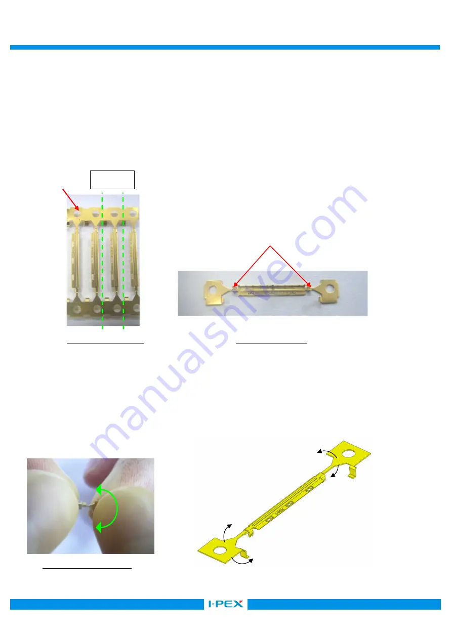
キャリアを金属用はさみ等を用いて下左写真の Cut Line(緑線)にて切断する。 
Cut carrier on the cut line of a lower left picture (green line) by a scissor for metal. 


Photo 10 Before cut                                              Photo 11 After cut 


METAL COVER の中心部を持ち、±45°で往復させてノッチ部から切り離します。 

もし、切り離れない場合は、この往復動作を繰り返して切り離します。(Photo 12) 
切り離し後はノッチ折り取り部にバリ発生なきことを確認してください。(Photo 13) 

Hold the center of METAL COVER and bend it 45 degrees back and forth to cut it from Notch. 
If it is not separated, bend it again.  (Photo 12) 
After separated, check if there is no burr around the cut part.(Photo 13) 


Photo 12 Cut condition 


Carrier 

Notch 

45° 

45

45° 

45° 

Cut Line 

Summary of Contents for CABLINE-UA II PLUG

Page 1: ...Part No 20496 Assembly Manual 4 S19433 July 8 2019 S Yamaguchi T Kurachi H Ikari 3 S18098 January 30 2018 R Hoshino K Tanaka M Takemoto 2 S17547 July 27 2017 R Hoshino K Tanaka M Takemoto 1 S12558 De...

Page 2: ...Pulse heat condition 3 1 Fixtures Pulse heater Heater chip 26P 32P 40P 50P Thickness 0 3 0 05 0 mm Width 8 8 0 03 0 mm 10 6 0 03 0 mm 13 0 0 03 0 mm 16 0 0 03 0 mm Recommended solder bar Resin free so...

Page 3: ...ds 2nd 2nd heat temperature 340 350 2nd 2nd rise time 0 5 seconds 2nd 2nd holding time 3 0 seconds Heater tip Pressure 12 15 N This pulse heat condition was evaluated and confirmed by our pulse heat j...

Page 4: ...k procedures 4 1 Soldering of center conductor First process the cable end as shown below Micro coax cable Part No B C E 20496 26 3 6 8 1 9 0 20496 32 4 5 9 9 10 8 20496 40 5 7 12 3 13 2 20496 50 7 2...

Page 5: ...sembly Manual Document No ASM 09004 5 14 Confidential C Discrete cable Part No B C E 20496 26 3 6 8 1 9 0 20496 32 4 5 9 9 10 8 20496 40 5 7 12 3 13 2 20496 50 7 2 15 3 16 2 a AWG 39 0 102 Unit mm Cab...

Page 6: ...ea Please confirm all contacts were applied flux Photo 2 After applying flux Photo 3 Please do not apply flux too much like Photo 3 It can cause flux splash or leak to the mating area Photo 3 Extra fl...

Page 7: ...ace a solder bar at center of connector HOUSING ASS Y Fig 1 Placing solder bar Set the cable Fig 2 Setting cable MCX Discrete cable Jacket When using a discrete cable set it so that the end of the jac...

Page 8: ...E UA II PLUG Assembly Manual Document No ASM 09004 8 14 Confidential C Photo 4 5 Solder center conductors with a pulse heater For soldering condition see photo 4 and 5 Photo 4 AWG 44 Photo 5 Expansion...

Page 9: ...If the short circuit can t be repaired use the soldering iron and repair it Failed point only Condition of Soldering iron 50 W Operating temperature 350 380 Application time of soldering iron 5 Within...

Page 10: ...er from carrier Cut Line Cut carrier on the cut line of a lower left picture green line by a scissor for metal Photo 10 Before cut Photo 11 After cut METAL COVER 45 Photo 12 Photo 13 Hold the center o...

Page 11: ...METAL COVER Detail of Notch Photo 14 Bottom side view Photo 15 Upper side view Caution By pulling like photo below to cut off by force Red arrow direction burrs and transformation can be caused Photo...

Page 12: ...r Fig 4 Assembly of METAL COVER Discrete cable METAL COVER When using a discrete cable please Apply an insulating tape to the connection before assemble METAL COVER Fig 5 Assembly of METAL COVER Slits...

Page 13: ...int and Photo 17 1 METAL COVER Housing 0 05 mm Max 2 METAL COVER 4 Check point 1 The amount of floats from housing surface 0 05 mm Max 2 Four nails of METAL COVER have fitted into four slits of housin...

Page 14: ...ig 5 Fig 6 8 Solder holes of METAL COVER 3 positions and Ground Bar with the soldering iron Fig 5 points Refer to Fig 6 for a limit of the solder height For conditions of soldering iron refer to sheet...

Reviews: