background image


CABLINE-UY Connector (Wire Type Plug) Instruction Manual


Document No. 

HIM-18037


2

  / 

7


Confidential C                                                                   

弊社、CABLINE-UY Connector(Wire type)の取り扱いに際して、本コネクタを安全に御使用頂くことを目的とし 
コネクタの挿入・抜去の手順及び注意点を記述致します。 
This manual explains the insertion & withdrawal methods and provides cautions to handle our CABLINE-UY 
connector (Wire type plug) properly and safely.   


【コネクタ型番】  (Connector parts No.)   

CABLINE-UY PLUG:              20857-0**T-0* 
CABLINE-UY RECEPTACLE: 20854-0**E-0* 
 

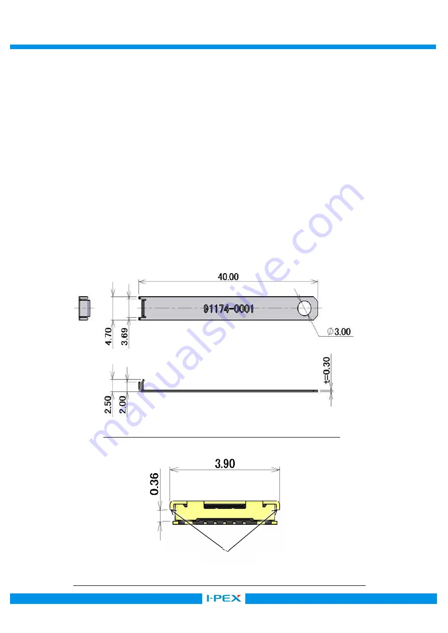
【挿抜 JIG について】  (Pushing and Pulling JIG)   

挿抜を行う際、ケ-ブルコネクタ首部へのストレスを避ける為、下図(Fig. 1)の形状の様な JIG を御使用下さい。 
ケ-ブル側コネクタには JIG 専用の引っかけ形状が設置されています。(Fig. 2) 
In mating/unmating, a special jig shown in Fig. 1, is recommended to avoid excessive stress to   
a cable connection point.   
The cable connector is designed to hook this “Pushing and Pulling JIG”. (Fig. 2) 


Fig. 1  推奨  抜去 JIG (Recommended Pushing and Pulling JIG) 

HOOK 

Fig. 2  抜去 JIG 引っかけ形状配置図  / PLUG connector with hooks for pulling jig 

Summary of Contents for CABLINE-UY 20857-0 T-0 Series

Page 1: ...FDE09 03 REV 8 CABLINE UY Connector Wire Type Plug Part No 20857 0 T 0 20854 0 E 0 Instruction Manual 1 S20033 January 20 2020 Y Fukumoto T Yamauchi Y Shimada 0 S19022 January 9 2019 Y Imaji K Yufu K...

Page 2: ...plug properly and safely Connector parts No CABLINE UY PLUG 20857 0 T 0 CABLINE UY RECEPTACLE 20854 0 E 0 JIG Pushing and Pulling JIG Fig 1 JIG JIG Fig 2 In mating unmating a special jig shown in Fig...

Page 3: ...Place a cable connector on a PCB connector as shown in Fig 4 Then move connectors left and right and back and forth slightly to make sure the connectors are firmly set How to mate Fig 5 Push the cente...

Page 4: ...t the stopper of the plug The jig should be holding the plug entirely Mating direction Fig 6 b Fig 6 c As shown in Fig 6 b place the plug above the receptacle to align mating direction When the connec...

Page 5: ...nnectors were misaligned as shown in Fig 7 b CAUTION Fig 8 a Fig 8 b Please make sure to set the cable side connector parallel to the board as shown in Fig 8 a If you mate in not parallel condition as...

Page 6: ...f the jig is removed when it is still touching the connector as shown in Fig 9 b the connectors may get unmated or mating may get incomplete How to withdraw cable connector Fig 10 a Slide the Pushing...

Page 7: ...ace Fig 11 CAUTION IN CABLE CONNECTOR HANDLING Fig 12 In the case of Fig 12 it has possibility to damage to the connector and come off from receptacle connector Especially when operator gives continuo...

Reviews: