background image


CABLINE-VS IIF Assembly Manual


Document No. 

ASM-17010


6

  / 

8


Confidential C                                                                   

3-3. FPC 半田付け  (FPC soldering) 

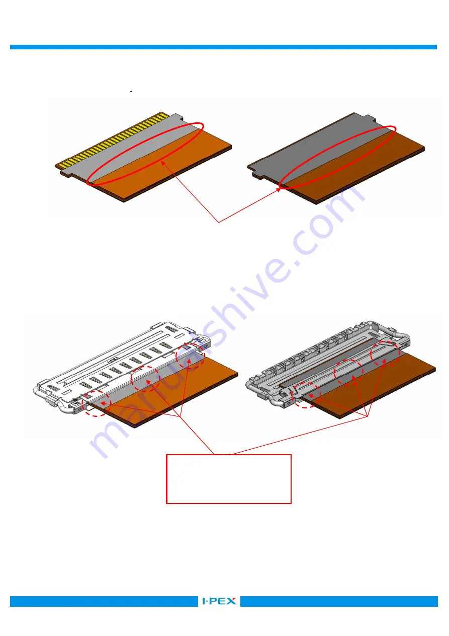
図 8 のように FPC に半田付け部を設け、上下面共に半田付けを必ず実施してください。 
Apply metallic material on top and bottom surfaces of the FPC to install soldering portion on the FPC. 


Fig.8 Soldering portions of the FPC 


SHELL と FPC を半田付けする(半田付け量の詳細は図 10 参照)。 
Solder shell and FPC. See Fig. 10 for the soldering amount. 


Fig.9 Soldered shell and FPC 


SHELL と FPC を半田付けする 
Soldering places 

Top view 

Bottom view 

Top view 

Bottom view 

Summary of Contents for CABLINE-VS IIF

Page 1: ...o ASM 17010 Confidential C I PEX Inc QKE DFFDE09 04 REV 8 CABLINE VS IIF Part No 20862 030T 01 Assembly Manual 0 S17805 November 1 2017 Y Miyazaki T Masunaga H Ikari Rev ECN Date Prepared by Checked b...

Page 2: ...IF connector 2 Applicable connector Name CABLINE VS IIF Parts No Discrete P N SHELL ASS Y 20862 030T 01 3 Work procedures 3 1 Connector delivery package SHELL ASS Y 1 Shell assemblies are delivered in...

Page 3: ...ELL This connector is used top contact point Face conductor side of the FPC upward and insert it into the shell horizontally as shown in Fig 3 Fig 3 FPC conducting side facing upward Caution 4 FPC Do...

Page 4: ...the FPC are positioned correctly before completing FPC insertion The FPC shall be inserted horizontally along the undersurface of the shell Fig 5 Fig 5 Checking FPC tab positions Caution FPC 6 FPC Mak...

Page 5: ...SHELL FPC 7 Shell lock checking point View A Make sure that shell locks on both ends of the shell are locking FPC properly Fig 7 Shell lock checking point Shell lock checking point Lock Locked Shell l...

Page 6: ...ly metallic material on top and bottom surfaces of the FPC to install soldering portion on the FPC Fig 8 Soldering portions of the FPC SHELL FPC 10 Solder shell and FPC See Fig 10 for the soldering am...

Page 7: ...010 7 8 Confidential C Fig 10 soldering of SHELL and FPC SOLDERING SOLDERING SHELL Make sure the red line areas just above the FPC touches solder OK Recommended soldering amount NG Insufficient solder...

Page 8: ...C Cautions for soldering CABLINE VS IIF 0 08mm FPC SHELL SHELL The thin connector thickness which is 0 08 mm may warp FPC shells during insertion Hold top and bottom surfaces of the shell with a jig b...

Reviews: