background image


CABLINE-VS IIF Assembly Manual


Document No. 

ASM-17010


8

  / 

8


Confidential C                                                                   

 
        ※半田付け時の注意事項  (Cautions for soldering) 
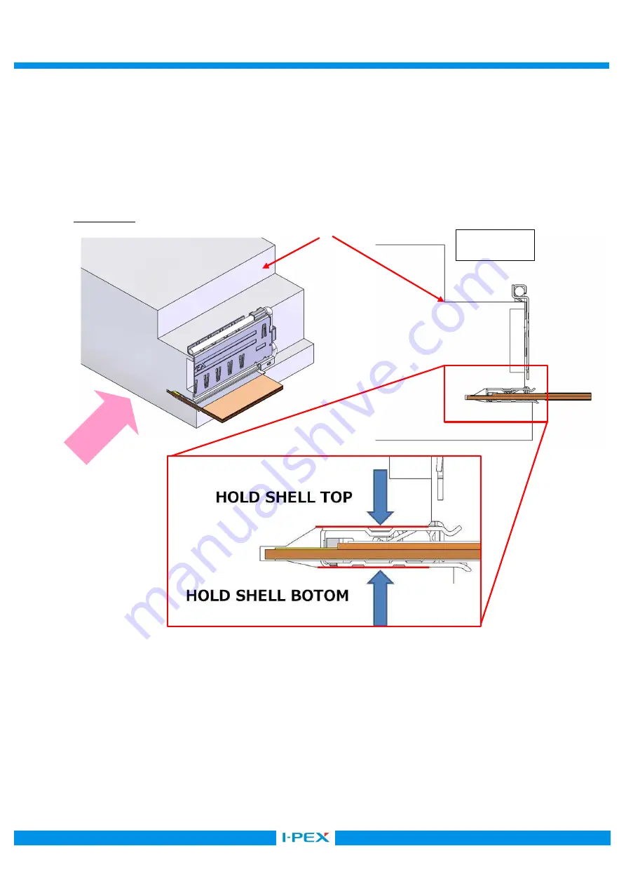
              CABLINE-VS IIF の板厚が 0.08mm であるため、FPC 挿入時に SHELL の上下が撓むことがあります。 
          半田付けを実施する際は、SHELL の上下面を押えて半田付けを行ってください。 

The thin connector thickness, which is 0.08 mm, may warp FPC shells during insertion. 


Hold top and bottom surfaces of the shell with a jig before soldering or mating failure may occur. 

 
                  例/Example 


View-B 

View-B 

JIG 

Summary of Contents for CABLINE-VS IIF

Page 1: ...o ASM 17010 Confidential C I PEX Inc QKE DFFDE09 04 REV 8 CABLINE VS IIF Part No 20862 030T 01 Assembly Manual 0 S17805 November 1 2017 Y Miyazaki T Masunaga H Ikari Rev ECN Date Prepared by Checked b...

Page 2: ...IF connector 2 Applicable connector Name CABLINE VS IIF Parts No Discrete P N SHELL ASS Y 20862 030T 01 3 Work procedures 3 1 Connector delivery package SHELL ASS Y 1 Shell assemblies are delivered in...

Page 3: ...ELL This connector is used top contact point Face conductor side of the FPC upward and insert it into the shell horizontally as shown in Fig 3 Fig 3 FPC conducting side facing upward Caution 4 FPC Do...

Page 4: ...the FPC are positioned correctly before completing FPC insertion The FPC shall be inserted horizontally along the undersurface of the shell Fig 5 Fig 5 Checking FPC tab positions Caution FPC 6 FPC Mak...

Page 5: ...SHELL FPC 7 Shell lock checking point View A Make sure that shell locks on both ends of the shell are locking FPC properly Fig 7 Shell lock checking point Shell lock checking point Lock Locked Shell l...

Page 6: ...ly metallic material on top and bottom surfaces of the FPC to install soldering portion on the FPC Fig 8 Soldering portions of the FPC SHELL FPC 10 Solder shell and FPC See Fig 10 for the soldering am...

Page 7: ...010 7 8 Confidential C Fig 10 soldering of SHELL and FPC SOLDERING SOLDERING SHELL Make sure the red line areas just above the FPC touches solder OK Recommended soldering amount NG Insufficient solder...

Page 8: ...C Cautions for soldering CABLINE VS IIF 0 08mm FPC SHELL SHELL The thin connector thickness which is 0 08 mm may warp FPC shells during insertion Hold top and bottom surfaces of the shell with a jig b...

Reviews: