


CABLINE
®
-VS Instruction Manual
Document No.
HIM-08004
10
/
16
Confidential C
【コネクタ抜去手順
/ Connector Un-mating Method. /
连接器拔出方法
】
・コネクタを抜去する。
Un-mating the connector. /
将连接器拔出
。
図
8
のように基板側コネクタに対し、ケーブル側コネクタの両側を矢印方向に平行に抜去する。
As shown in Fig.8, hold both ends of the cable side connector and un-mating it parallel to the arrowed direction from the PCB side
connector.
如图
8
所示,将线端的连接器从板端的连接器沿着箭头所示方向水平拔出。
平行抜去
OK
状態
/ parallel un-mating OK condition
こじり抜去
NG
状態
/ Slanted un-mating NG condition
水平拔出
OK
状态
斜着拔出
NG
状态
図
8
(
Fig.8
)
PULL TAPE
付
PULL BAR
の場合
/ For the connector with PULL BAR with PULL TAPE. /
在拉环上贴有胶带的情况
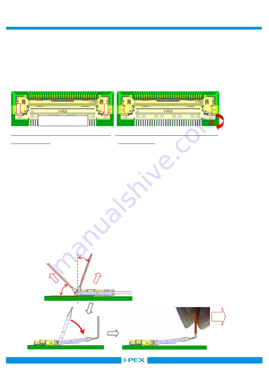
まず、
PULL-TAPE
を①の方向に引っ張り、基板側コネクタとのロックを解除後、
②の方向に
PULL BAR
を回転させ、基板に平行に③の方向に引っ張り、抜去を行う。
注意:
×印の方向へ
PULL-TAPE
を持ち上げようとすると、コネクタが破損する恐れがあります。
First, pull PULL-TAPE to the direction
①
and release the lock with the PCB connector. Then, turn PULL BAR to the direction
②
and pull
it to the direction
③
in parallel with PCB to un-mate the connector.
Caution: In pulling PULL-TAPE to the direction
×
mark, there are possibilities to cause
the PCB connector deformation
首先,将胶带向着
①
的方向拉出,使拉环与板端的连接器的锁扣解除以后,按照
②
的方向将拉环
旋转,使其与
PCB
基板平行。最后沿着
③
的方向将连接器拔出。
注意
:
如果沿着
×
印的方向向上拉出胶带,可能会导致连接器破损。
図
9
(
Fig.9
)
Withdrawal direction
×
0
°~
60
°
0
°~
90
°
①
②
③


