


CABLINE
®
-VS Instruction Manual
Document No.
HIM-08004
15
/
16
Confidential C
・ケーブルコネクタの取り回しの際には特定のケーブルに引っ張り力が集中しないように配慮ください。
・コネクタのケーブル取り付け部に引っ張り力及び繰り返し変位が加わらないように配慮ください。
・
In a cable harnessing work, be careful NOT to apply the pulling force to specific cables.
・
Be careful NOT to apply the pulling force or repeated bending force to the cable attachment part of a plug connector.
・
将
Cable
整形成特定的形状时,应该避免特定的
Cable
产生集中的受力。
・
在靠近连接器部分的
Cable
上不要施加拉力或者持续的震动。
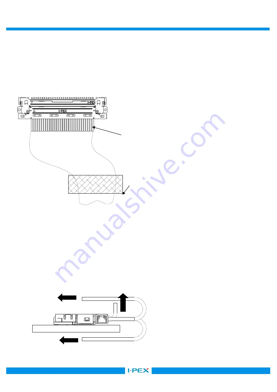
図
13 (Fig.13)
・
図
14
のように、矢印方向に常に力が加わるようなケーブルの引き回しを行うと、嵌合外れやコネクタの破損等
の恐れがありますので、ご注意願います。
・
Continuous force of the direction shown in black arrow in Fig. 14 can damage connectors or cause the coming off from receptacle connector.
Please be careful NOT to apply such force.
・
请注意,避免如图
14
所示的那样沿着箭头方向在
Cable
上施加外力使
Cable
发生转向,因为这样做
会使连接器产生脱落或者损坏。
図
14(Fig.14)
ケーブルを固定し、コネクタのケーブル取り付け部に外
力が加わらないように配慮ください。
Fix the cable so that the external force is NOT
applied to the cable attachment part of connector.
将此处的
Cable
进行固定,为了使在靠近连接器部分
コネクタのケーブル取り付け部
Cable attachment part of Connector.
靠近连接器部分的
Cable


