background image


CABLINE-VSF Assembly Manual


Document No. 

ASM-13003


2

  / 

9


Confidential C                                                                   

 
1.  目的  (Purpose): 
      CABLINE-VSF において、FPC の組み付けについて明記する。 
      This manual is to explain the process of CABLINE-VSF assembly of FPC. 
 
2.  適用コネクタ  (Applicable connector): 
            Name: CABLINE-VSF 
                Parts No.:   

Discrete P/N 

PLUG SHELL ASS’Y (With LOCK BAR) 

20645-0**T-01 

PLUG SHELL (Without LOCK BAR) 

3049-0**1 


3.  作業手順  (Work procedures): 

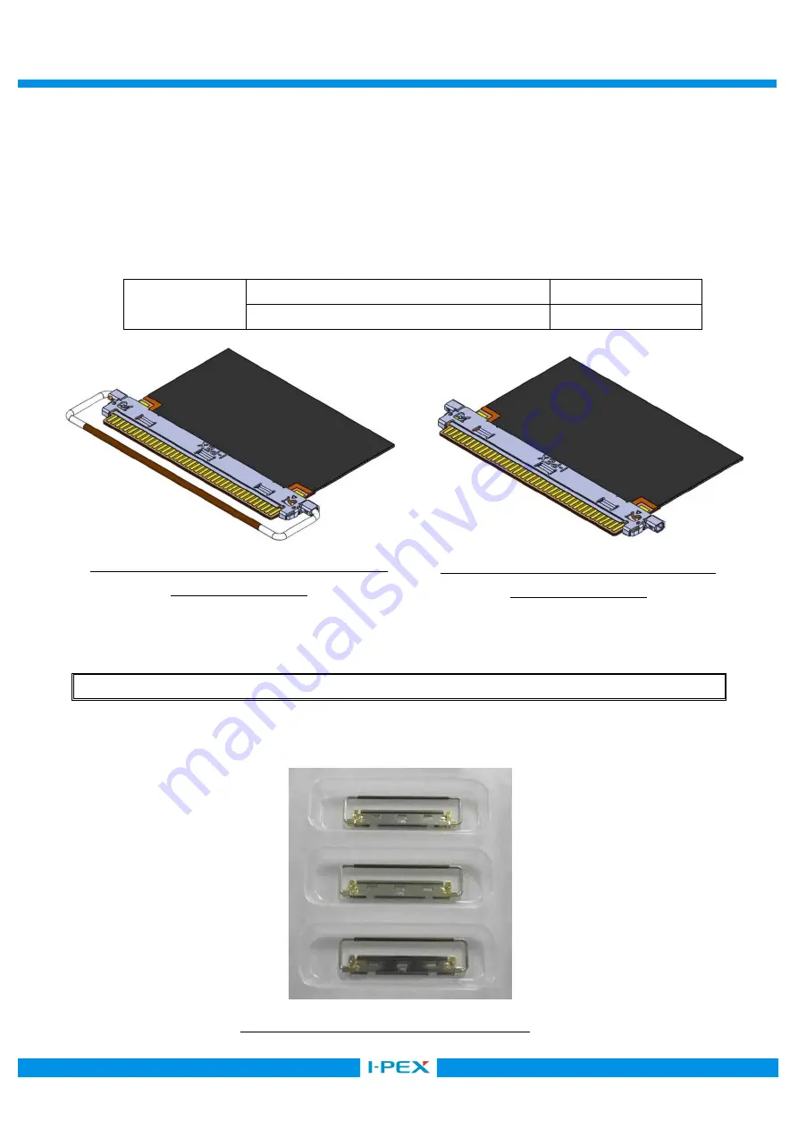
3-1.  コネクタ納品状態及び取り扱い注意事項  (Connector delivery state and cautions in treating connector) 


SHELL ASS’Y は写真 1 のようにトレーに梱包された状態にて納品されます。キャリアカット等は不要です。 

SHELL ASS’Y is delivered to the tray in the packed state as shown in photo 1. Carrier cut is unnecessary. 


PLUG SHELL ASS’Y(LOCK BAR 付)の場合  / PLUG SHELL ASS’Y(With LOCK BAR).


Fig 1. PLUG SHELL ASS’Y (With LOCK BAR) 

FPC Assembly State 

Fig 2. PLUG SHELL (Without LOCK BAR) 

FPC Assembly State 

Photo 1. PLUG SHELL ASS’Y delivery state 

Summary of Contents for CABLINE-VSF

Page 1: ...645 0 T 01 3049 0 1 Assembly Manual 4 S19531 September 13 2019 T Onishi T Masunaga H Ikari 3 S14534 December 22 2014 H Aoki J Tateishi E Kawabe 2 S14425 October 16 2014 H Ikari J Tateishi E Kawabe 1 S...

Page 2: ...20645 0 T 01 PLUG SHELL Without LOCK BAR 3049 0 1 3 Work procedures 3 1 Connector delivery state and cautions in treating connector SHELL ASS Y 1 SHELL ASS Y is delivered to the tray in the packed st...

Page 3: ...ine green line as shown in photo 2 by a scissors for metal SHELL 45 1 5 Hold the center of SHELL and cut it off from Notch by 45 deg of reciprocating work When it does not be cut try again this recipr...

Page 4: ...f Notch 8 Caution Please do not pull forcibly SHELL and Carrier as shown in Photo 8 Red arrow direction it cause the burr and transformation Photo 6 Bottom side view Photo 7 Upper side view Photo 8 Cu...

Page 5: ...S Y With LOCK BAR and SHELL Without Lock Bar perform similar procedure 3 2 FPC Assembly of FPC 3 FPC SHELL Please set FPC to SHELL horizontally as shown in Fig 3 4 FPC Please do not insert FPC that th...

Page 6: ...L undersurface Fig 5 FPC inserting method 2 1 Caution 1 FPC 6 FPC Please insert FPC horizontally If FPC is slanted as shown in Fig 6 it cause the breakage of FPC Fig 6 FPC insertion Bad example 2 FPC...

Page 7: ...A It confirms whether FPC is being assembled normally Check SHELL Lock condition to judge that FPC is assembled normally Fig 7 point and View A Fig 7 Confirmation of FPC assembly Point View A Point Vi...

Page 8: ...n If it need to increase the FPC holding force from SHELL perform the FPC soldering When perform the FPC soldering FPC need the soldering part as shown in Fig 8 Fig 8 Soldered part of FPC SHELL FPC 9...

Page 9: ...9 9 Confidential C X SOLDERING SOLDERING OK Sufficient solder 0 10MAX FPC SHELL Please solder until the soldered part of FPC contacts SHELL red line part NG Insufficient solder Fig 9 Sufficient solde...

Reviews: