background image


CABLINE-VSF Assembly Manual


Document No. 

ASM-13003


7

  / 

9


Confidential C                                                                   

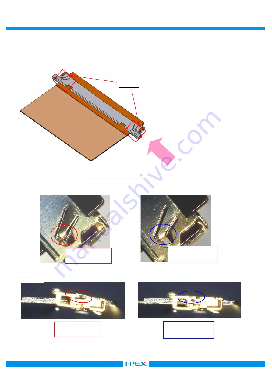
        ③FPC が正常に組み立てられているか確認する。 

        SHELL のロック状態で正常に組み立てられているか確認する。  (図 7  ★point 及び View-A) 

It confirms whether FPC is being assembled normally. 
Check SHELL Lock condition to judge that FPC is assembled normally. (Fig.7  ★point and View-A) 


Fig 7. Confirmation of FPC assembly 

Point 

View-A 
 

Point 

View-A 


Unlock 状態   

Unlock condition 

正常 Lock 状態 

Lock condition. 

Unlock 状態   

Unlock condition 

正常 Lock 状態 

Lock condition. 

Summary of Contents for CABLINE-VSF

Page 1: ...645 0 T 01 3049 0 1 Assembly Manual 4 S19531 September 13 2019 T Onishi T Masunaga H Ikari 3 S14534 December 22 2014 H Aoki J Tateishi E Kawabe 2 S14425 October 16 2014 H Ikari J Tateishi E Kawabe 1 S...

Page 2: ...20645 0 T 01 PLUG SHELL Without LOCK BAR 3049 0 1 3 Work procedures 3 1 Connector delivery state and cautions in treating connector SHELL ASS Y 1 SHELL ASS Y is delivered to the tray in the packed st...

Page 3: ...ine green line as shown in photo 2 by a scissors for metal SHELL 45 1 5 Hold the center of SHELL and cut it off from Notch by 45 deg of reciprocating work When it does not be cut try again this recipr...

Page 4: ...f Notch 8 Caution Please do not pull forcibly SHELL and Carrier as shown in Photo 8 Red arrow direction it cause the burr and transformation Photo 6 Bottom side view Photo 7 Upper side view Photo 8 Cu...

Page 5: ...S Y With LOCK BAR and SHELL Without Lock Bar perform similar procedure 3 2 FPC Assembly of FPC 3 FPC SHELL Please set FPC to SHELL horizontally as shown in Fig 3 4 FPC Please do not insert FPC that th...

Page 6: ...L undersurface Fig 5 FPC inserting method 2 1 Caution 1 FPC 6 FPC Please insert FPC horizontally If FPC is slanted as shown in Fig 6 it cause the breakage of FPC Fig 6 FPC insertion Bad example 2 FPC...

Page 7: ...A It confirms whether FPC is being assembled normally Check SHELL Lock condition to judge that FPC is assembled normally Fig 7 point and View A Fig 7 Confirmation of FPC assembly Point View A Point Vi...

Page 8: ...n If it need to increase the FPC holding force from SHELL perform the FPC soldering When perform the FPC soldering FPC need the soldering part as shown in Fig 8 Fig 8 Soldered part of FPC SHELL FPC 9...

Page 9: ...9 9 Confidential C X SOLDERING SOLDERING OK Sufficient solder 0 10MAX FPC SHELL Please solder until the soldered part of FPC contacts SHELL red line part NG Insufficient solder Fig 9 Sufficient solde...

Reviews: