
CABLINE-VSF CONN. Instruction Manual
Document No.
HIM-13010
5
/
12
Confidential C
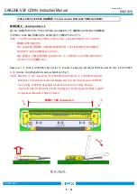
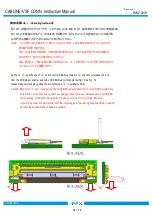
図
6
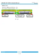
のように仮挿し状態時に、
LOCK BAR
を基板側コネクタ側に回転させ、
FPC
を水平に押す。
そして、突き当て面に隙間がないか確認する。
From temporary inserting condition as shown in Fig.6, turn LOCK BAR to the PCB connector side and push FPC horizontally. Then, confirm
whether there is space between mating confirmation surfaces.
図
6
(
Fig.6
)
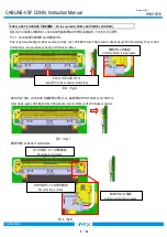
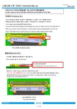
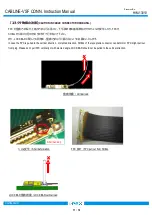
嵌合が完了後、
LOCK BAR
を基板側に押し込み、基板側コネクタの
SHELL
とロックさせる。
After mated, push LOCK BAR to the PCB side and lock it to SHELL of the PCB side connector.
図
7
(
Fig.7
)
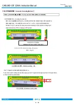
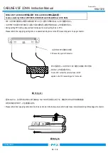
確認内容
Contents of confirmation.
:
図
8
(
Fig.8
)
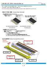
SHELL ASS’Y(LOCK BAR
付
)
の場合
/ For the connector SHELL ASS’Y(With LOCK BAR).
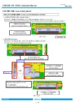
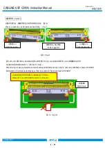
FPC
を水平に挿入する
Insert FPC to the connector horizontally.
隙間がないか確認
Confirm whether there is space.
隙間がないか確認
Confirm whether there is space.
ロックが掛かっている事を確認
Check the lock is locked.
ロックが掛かっている事を確認
Check the lock is locked.


