
CABLINE-VSF CONN. Instruction Manual
Document No.
HIM-13010
9
/
12
Confidential C
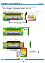
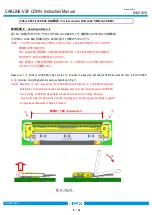
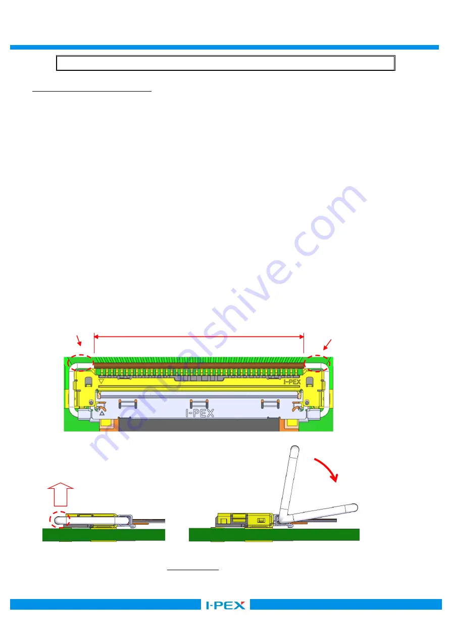
抜去手順Ⅰ
/
Un-mating method
Ⅰ
図
12
の①の箇所のどちらか一方を②の方向に
LOCK BAR
を上げ、基板側コネクタとのロックを解除後、
③の方向に
LOCK BAR
を回転させる。抜去は図
11
と同様の方法にて行う。
注意:
①以外で
LOCK-BAR
を②方向に上げようとすると、
LOCK BAR
が変形したり、コネクタが
破損する恐れがあります。
また、
LOCK BAR
の絶縁コート部を抜去に使用すると、
LOCK BAR
が変形する可能性が
ありますので、抜去には使用しないでください。
なお、絶縁コート部に金属や硬いものを当てると、コートが剥がれてしまう恐れがありますので、
当てないようにご注意願います。
Raise one of
①
points of LOCK BAR in Fig.12 to the
②
direction to release the lock with the PCB side connector, then, turn LOCK BAR
to
③
direction. Un-mating method is same as described in Fig.11.
Caution: Except for
①
part, if you pull up the LOCK-BAR towards direction
②
, LOCK BAR would have
deformation or the connector would have damage. Also, if you use Insulated part of LOCK BAR
for Un-mating, LOCK BAR may deform. Please do not use it for Un-mating. Moreover,
if you hit the metal or hard material onto the insulating part, the coating have possibility to peel off
so that please understand to handle it carefully.
図
12
(
Fig.12
)
SHELL ASS’Y(LOCK BAR
付
)
の場合
/ For the connector SHELL ASS’Y(With LOCK BAR).
③
①
①
②
絶縁コート部
/ Insulated part.


