background image


EVAFLEX 5-SE-GHT Connector Instruction Manual


Document No. 

HIM-18018


8

  / 

9


Confidential C                                                                   

<注

5

Caution 5


解除ボタンを押さずに

FFC/FPC

の抜去

(

無理抜き

)

はしないで下さい。

(

3-6 )FFC/FPC

及びコネクタを破損させる


原因となります。

(

写真

  3-2 )


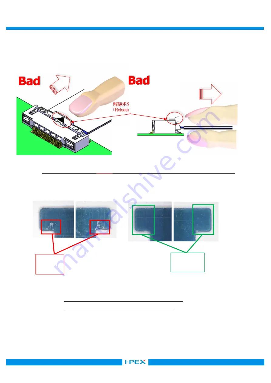
Do not forcedly withdraw FFC/FPC without pushing a release button, as this may damage FFC/FPC or the connector. 


3-6 FFC/FPC

抜去方法

  ( 

NG

  4

 ) / Fig.3-6 Withdrawing FFC/FPC Without Pushing Release Button 

ダメージ


/ Damage 

(b) Properly Withdrawn FFC 

(a) Improperly withdrawn FFC 

ノーダメージ


/ No Damage 

写真

.3-2. (a)

無理抜きを行った場合

  (b)

正常抜去を行った場合


Photo.3-2 Comparing Properly/ Improperly Withdrawn FFC 

解除ボタンが押せていない


/ Releasing button is not pushed 

Summary of Contents for EVAFLEX 5-SE-GHT

Page 1: ...o HIM 18018 Confidential C I PEX Inc QKE DFFDE09 03 REV 8 EVAFLEX 5 SE GHT Part No 20899 0 E 01 Instruction Manual 0 S19209 March 26 2019 M Nakamura T Kurachi H Ikari Rev ECN Date Prepared by Checked...

Page 2: ...le EVAFLEX 5 SE GHT connector properly and safely connector Product Name EVAFLEX 5 SE GHT Part No 20899 0 E 01 Note1 Note 1 Connector position number Labelled Diagram of the Connector Mating throttle...

Page 3: ...so that the pattern faces PCB side as shown in Figure 2 1 insert it parallel to the PCB 2 1 FFC FPC 1 Fig 2 1 FFC FPC Pattern Facing Correct Direction 2 2 FFC FPC NG 1 Fig 2 2 FFC FPC Pattern Facing W...

Page 4: ...wable angle is maximum 10 degrees Fig 2 4 a Slightly insert the connector Connector pitch direction without applying excessive load Insert FFC FPC fully until it is vertical to the connector 2 4 b 15...

Page 5: ...ck or may deform connector or FFC FPC 2 Caution 2 2 6 15 FFC FPC Do not exceed 15 degrees angle or it will not be locked nor may deform connector or FFC FPC 2 5 FFC FPC NG 2 Fig 2 5 Bad FFC FPC insert...

Page 6: ...e button Fig 3 2 FFC Pinch release button and FFC FPC 3 1 FFC FPC 1 Fig 3 1 Pushing Release Button Push release button Push 3 2 FFC FPC 2 Fig 3 2 Withdrawing FFC FPC FFC FPC 3 3 FFC FPC FFC FPC 3 1 Wi...

Page 7: ...rt circuit 4 Caution 4 Do not push the release button using the nails it may deform nor cause short circuit 3 4 FFC FPC NG 2 Fig 3 4 Bad Ways to Push Release Button 3 5 FFC FPC NG 3 Fig 3 5 Bad Ways t...

Page 8: ...dly withdraw FFC FPC without pushing a release button as this may damage FFC FPC or the connector 3 6 FFC FPC NG 4 Fig 3 6 Withdrawing FFC FPC Without Pushing Release Button Damage b Properly Withdraw...

Page 9: ...his may damage FFC FPC or the connector See Photo 4 1 FFC FPC FFC FPC FFC FPC Do not apply excessive force to the connector and FFC FPC or they may be damaged FFC FPC FFC FPC Do not pull around FFC FP...

Reviews: