


ISH & ISHV & ISHVS CONNECTOR Instruction Manual
Document No.
HDM-0002
28
/
29
Confidential C
12. Storage of housings and terminals
①
Store housings and terminals in a warehouse which is controlled temperature and humidity.
(Recommend : Temperature 27
℃
MAX. , Humidity 65%MAX.)
②
Store housings in a cardboard box. Avoid storing in a way that may cause damage to the boxes, e.g. placing boxes on top of other boxes or
storing in a precarious way to cause the boxes to fall.
Housing may be deformed if the boxes have been damaged.
③
Store terminals in a cardboard box. Avoid storing in a way that may cause damage to the boxes, e.g. placing boxes on top of other boxes or
storing in a precarious way to cause the boxes to fall.
Reel(s) or terminal(s) may be deformed if the boxes have been damaged.
13. Jig
①
Use the jig specialized for releasing the secondary lock part, for releasing the retainer and for removing terminals.
②
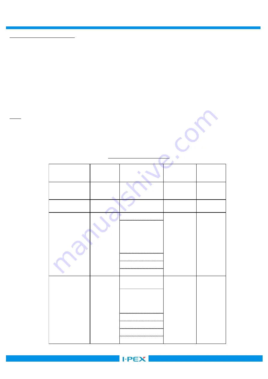
Table 7 shows the name of the releasing jig and their part number
③
To purchase any of the jigs, please contact the Sales Dept. of our company at the following in 15(Sheet 29).
ISH 10P
:
V0020-91010-211
ISH 12P
:
V0016-91012-211
V0016-91012-212
V0016-91012-214
V0016-91012-215
V0016-91012-216
V0016-91012-217
V0016-93012-211
ISH 16P
:
V0016-91016-211
ISH 20P
:
V0020-91020-211
ISH 26P
:
V0020-91026-211
ISH 6P
:
V0016-91006-211
V0016-91006-212
ISHV 8P
:
V0027-91008-211
ISHV 12P
:
V0027-91012-211
ISHV 16P
:
V0027-91016-211
ISH 20P
:
V0016-91020-211
Remove terminals
All female housing
Sheet 21-22
AP0004-01-005
Retainer releasing jig
Release retainer
Sheet 20
AP0004-02-001
Jig Name
Procedures
Female housing Part No.
Procedures detailed on
Jig Part No.
Female terminal releasing Jig
Retainer releasing jig
Release retainer
Sheet 20
AP0031-02-001
ISH 8P
:
V0020-91008-212
V0020-91008-213
V0020-91008-214
V0020-91008-215
V0020-91008-216
Rear holder releasing Jig
Release rear holder
ISH 3P
:
V0013-91003-211
ISHV 3P
:
V0037-91003-211
Sheet 19
AP0004-08-002
Table 7. Releasing jig & Part No.


