background image


ISH HYBRID CONNECTOR Instruction Manual


Document No. 

HDM-0009 


23

  / 

24


Confidential C                                                                                                                                                                                                   


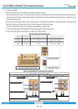
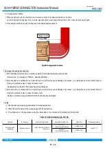
11-2. Arrangement of Wires 


When arranging the wires horizontally, to avoid excessive stress to the sidewalls and female terminals,   

and the female terminal leaning in the core hole, please keep the wires straight (at least 15mm) from connector as shown in Fig46.


Once straight portion is secured, arrange the wires with adequately large R. 


12.Storage of housings and terminals 


Store housings and terminals in a warehouse which is controlled temperature and humidity. 

          (Recommend : Temperature 27

MAX. , Humidity 65%MAX.) 


Store housings in a cardboard box. Avoid storing in a way that may cause damage to the boxes, e.g. placing boxes on top of other boxes or 

storing in a precarious way to cause the boxes to fall. 


Housing may be deformed if the boxes have been damaged.   


Store terminals in a cardboard box. Avoid storing in a way that may cause damage to the boxes, e.g. placing boxes on top of other boxes or 

storing in a precarious way to cause the boxes to fall. 


Reel(s) or terminal(s) may be deformed if the boxes have been damaged. 


13.Jigs 

  Use the terminal releasing jig specialized for releasing terminals. 

  Table 7 shows the name of the releasing jig and their part number     

  To purchase any of the jigs, please contact the Sales Dept. of our company at the following in 15(sheet 24).   


Female Terminal

releasing jig

Releasing Terminal

ISH20P HIBRID:V0072-020B-111

                           V0072-020B-112

AP0004-01-005

sheet 15

17

VT004-513

(1.5mm Female Terminal)

AP0037-01-001

VT001-512

(0.5mm Female Terminal)

Jig Name

Procedurees

Female Housing Part No.

Female Terminal Part No.

Jig Part No.

Procedures detailed on

Fig 46. Arrangement of wires   

Table 7.Terminal releasing jig & Part No.   

Straight portion 

Summary of Contents for ISH20P

Page 1: ...RID CONNECTOR Instruction Manual 3 RS0743 September 18 2020 H Naoi J Tateishi E Kawabe 2 RS0612 July 9 2019 S Tanaka S tono E Kawabe 1 RS0550 December 18 2018 S Tanaka S tono T Osuga 0 RS0412 November...

Page 2: ...lation 6 How to release the retainer 7 How to release female terminals 8 Rear cover installation 9 Mating of connector 10 Unmating of connector 11 Handling of Product 12 Storage of housings and termin...

Page 3: ...M 0009 3 24 Confidential C 1 Purpose The Manual explains the handling of ISH HYBRID CONNECTOR 2 Applicable items The Manual is applicable to the items listed below 0 5mm 1 5mm FEMALE TERMINAL VT001 51...

Page 4: ...cut off conductors short conductor and deformed conductors Using faulty wires may cause crimping problems VT004 513 1 5mm Part No Terminal Tab Size Applicable Wire VT001 512 0 5mm Wire Size 0 3mm2 0 5...

Page 5: ...shown in 15 sheet 24 about wire used then we will verify it and notify you the appropriate crimp dimensions VT004 513 0 5mm2 1 93mm MAX 1 00 0 05mm 1 60 0 05mm 2 00 mm 0 5mm 1 5mm Terminal Tab Size P...

Page 6: ...micrometer see Fig 5 Secure terminals firmly to obtain accurate measurement Do not pinch the bell mouth The wire barrel crimp height can not measure accurately 1 2 Measuring method for insulation barr...

Page 7: ...er see Fig 7 Secure terminals firmly to obtain accurate measurement Fig 7 Wire barrel Crimp width measurement 1 4 Measuring method for insulation barrel crimp width is described below To measure the i...

Page 8: ...Fig 10 and Table 3 Cut off tub Excess conductirs height Excess conductirs length Bellmouth height Bellmouth length E D C VT004 513 0 3 mm 1 2 0 05mm 1 30mm MAX 0 80mm MAX 0 20mm MAX VT001 512 0 2 mm...

Page 9: ...ned resulting in different dimension of excess conductors or bellmouth between the sides dimensions must be measured on larger side and be satisfied In the case shown in Fig 12 measure excess conducto...

Page 10: ...twist is J 1 2 from the wire barrel baseline see Fig 14 7 Bend up and Bend down Bend up is VT001 512 1 90mm MAX VT004 513 2 1mm MAX and no Bend down the hight from the wire barrel baseline to the term...

Page 11: ...ductors are insufficiently inserted into the wire barrel see Fig 18 3 Excessive conductors out Excess conductors protrude from the wire barrel and does not satisfy the dimension in Table3 of sheet 8 F...

Page 12: ...such as failure to be locked or short circuit between adjacent female terminals see Fig 21 5 Incomplete insulation crimping Strip length is too short and insulation is crimped inside the wire barrel s...

Page 13: ...the terminal retention is fastened by pulling the wire lightly towards you Notes Terminals must be inserted in the orientation instructed Forcibly inserting terminals in any other orientation may resu...

Page 14: ...t the retainer is pushed in completely i e aligned with the bottom surface of the housing When the retainer cannot be pushed in completely do not push forcefully Check that the terminals are inserted...

Page 15: ...Completed at the position where the releasing apertures comes out from the bottm surface of the female housing Therefore must not release the retainer anymore It may cause damage or deformation of th...

Page 16: ...then lever up the lance as shown in Fig 34 and 35 Keep the jig in the place and pull the terminal out by holding the wire If there is any difficulty in pulling out the terminal do not pull it forcefu...

Page 17: ...80 0 1mm Female Terminal Part No Terminal releasing jig Part No Dimensions 0 37 mm 1 5mm 0 5mm Terminal Tab Size 0 02 0 04 0 02 0 00 0 00 0 02 0 00 0 02 0 02 0 04 0 02 0 00 0 00 0 02 0 00 0 02 Fig34 C...

Page 18: ...formation on the terminal or the housing do not use the damaged item Replace the item with a new one Only use the terminal releasing jig specified Do not insert the releasing jig into the cavities see...

Page 19: ...is possible to install at 55N MAX It is possible to install the rear cover to the female housing which is either inserted or not inserted the terminals When handling the terminal inserted female hous...

Page 20: ...arm to prevent insufficient mating After that pull the female connector lightly to check that the female connector is locked Notes Only mate the connector in the direction instructed above Do not forc...

Page 21: ...isengaging the female connectors If there is any damage or deformation do not use the damaged item Replace the item with a new one 11 Handling of Product 11 1 Conductivity test 11 1 1 Male Connector W...

Page 22: ...has been inserted Replace the female terminal Probe pin must be bigger than the gap between female housing and female terminal see Table 6 Once tested check there is no deformation e g collapse etc of...

Page 23: ...boxes to fall Housing may be deformed if the boxes have been damaged Store terminals in a cardboard box Avoid storing in a way that may cause damage to the boxes e g placing boxes on top of other box...

Page 24: ...nd wires and that no rain water dust and dirt etc are present Handle products with care If there is any damage deformation discoloration etc to wires housings and any other parts do not use the damage...

Reviews: