background image


MINIFLEX 2-BF LK TYPE Instruction Manual


Document No. 

HIM-17036


7

  / 

13


Confidential C                                                                   


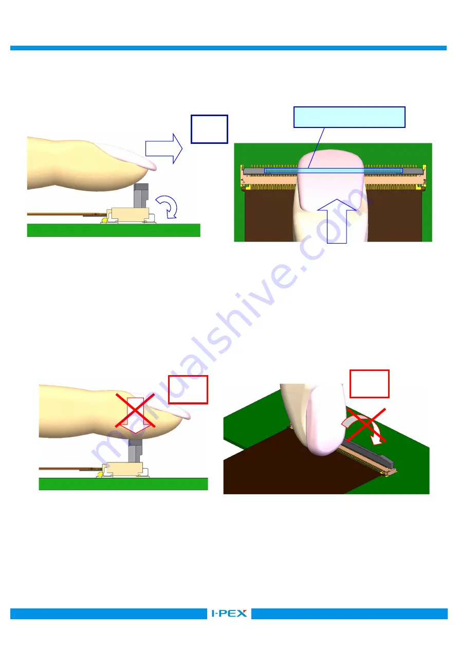
3.  アクチュエータのロック方法/To lock actuator 

アクチュエータの中央部を FPC 挿入方向から水平に、指の腹で押して下さい。 
Push the center of actuator to the arrowed direction horizontally with finger cushion   
from the FPC inserting direction. 


図 11.  アクチュエータのロック方法  (OK) / Fig.11 To lock actuator (OK) 


≪注意/Caution≫ 

・アクチュエータをロックする際、アクチュエータを上から押さえつけないで下さい。 

また、爪でアクチュエータをロックしないで下さい。 
アクチュエータが破損し、機能を損なう恐れがあります。 
Please do not press an actuator from a top and lock actuator by finger nail. 
Actuator is damaged and a function is not satisfied. 


図 12.  アクチュエータのロック方法  (NG) / Fig.12 To lock actuator (NG)


OK 

NG 

NG 

操作部/Operation area 

Summary of Contents for MINIFLEX 2-BF LK

Page 1: ...8 MINIFLEX 2 BF LK TYPE Part No 20817 E 01 Instruction Manual 2 S19622 October 2 2019 R Morita T Masunaga H Ikari 1 S18616 September 27 2018 Y Miyazaki T Masunaga H Ikari 0 S18223 April 2 2018 A Koyan...

Page 2: ...ndle our FPC connector MINIFLEX 2 BFLK TYPE properly and safely Connector Product Name MINIFLEX 2 BF LK TYPE Part No 20817 E 01 part shows the number of the connector position Names of each part of th...

Page 3: ...ect to the contact pressure and the reliability will not be damaged However there is the possibility that the insertion force rises in inserting FPC because the gap of contacts became narrowed Therefo...

Page 4: ...the connector Please confirm FPC is inserted into the end of mating part fully 4 FPC OK Fig 4 FPC insertion OK Caution 5 FPC If it becomes the short insertion and oblique insertion of FPC as shown in...

Page 5: ...The check of FPC insertion becomes easy by preparing the wing in FPC and preparing the silk print in board 6 FPC Fig 6 The check of FPC insertion Reference 7 FPC OK Fig 7 FPC insertion OK NG Short ins...

Page 6: ...push against housing both ends at 5N or more Housing is damaged 9 FPC NG Fig 9 FPC insertion NG FPC FPC Please do not press FPC near a connector Contact gives damage to FPC and contact is damaged It b...

Page 7: ...actuator to the arrowed direction horizontally with finger cushion from the FPC inserting direction 11 OK Fig 11 To lock actuator OK Caution Please do not press an actuator from a top and lock actuato...

Page 8: ...fidential C Please do not operate side of an actuator Actuator is damaged or it becomes imperfect lock 13 NG Fig 13 To lock actuator NG Please do not press contact on top by finger nail etc after a lo...

Page 9: ...ctuator after a lock actuator Connector and FPC are damaged It becomes the electrical connection NG 15 NG Fig 15 To lock actuator NG Please do not operate it using a sharp tool For example tweezers Co...

Page 10: ...ot press to the direction of FPC mating side Actuator and contacts are damaged 17 NG Fig 17 To release actuator NG Please do not operate side of an actuator Actuator is damaged 18 NG Fig 18 To release...

Page 11: ...from the end of FPC stiffener 19 FPC OK Fig 19 Flexion of FPC OK Caution FPC FPC FPC Please avoid applying excessive stress to the FPC connector exit part FPC stiffener with FPC inserted Housing and c...

Page 12: ...withdraw FPC Caution 1 FPC FPC Please refrain from withdrawing FPC with actuator close condition It may cause deformation of FPC 22 FPC NG Fig 22 To withdraw FPC NG 23 a b Fig 23 In case withdrawing...

Page 13: ...l C 7 Regarding board warp after mounting 90mm PCB 0 5mm JEITA ED 4702C Be careful that warp of 90mm width PCB is 0 5mm or less If excessive warp is applied Connector is damaged Reference standard JEI...

Reviews: