background image


NOVASTACK

®

 35-HDN    Instruction Manual


Document No. 

HIM-18019


5

  / 

8


Confidential C                                                                   

  3.取扱い上の注意/ Cautions for Handling the Component 
    3-1.基板-FPC での使用の場合/ Using for board to FPC connection.


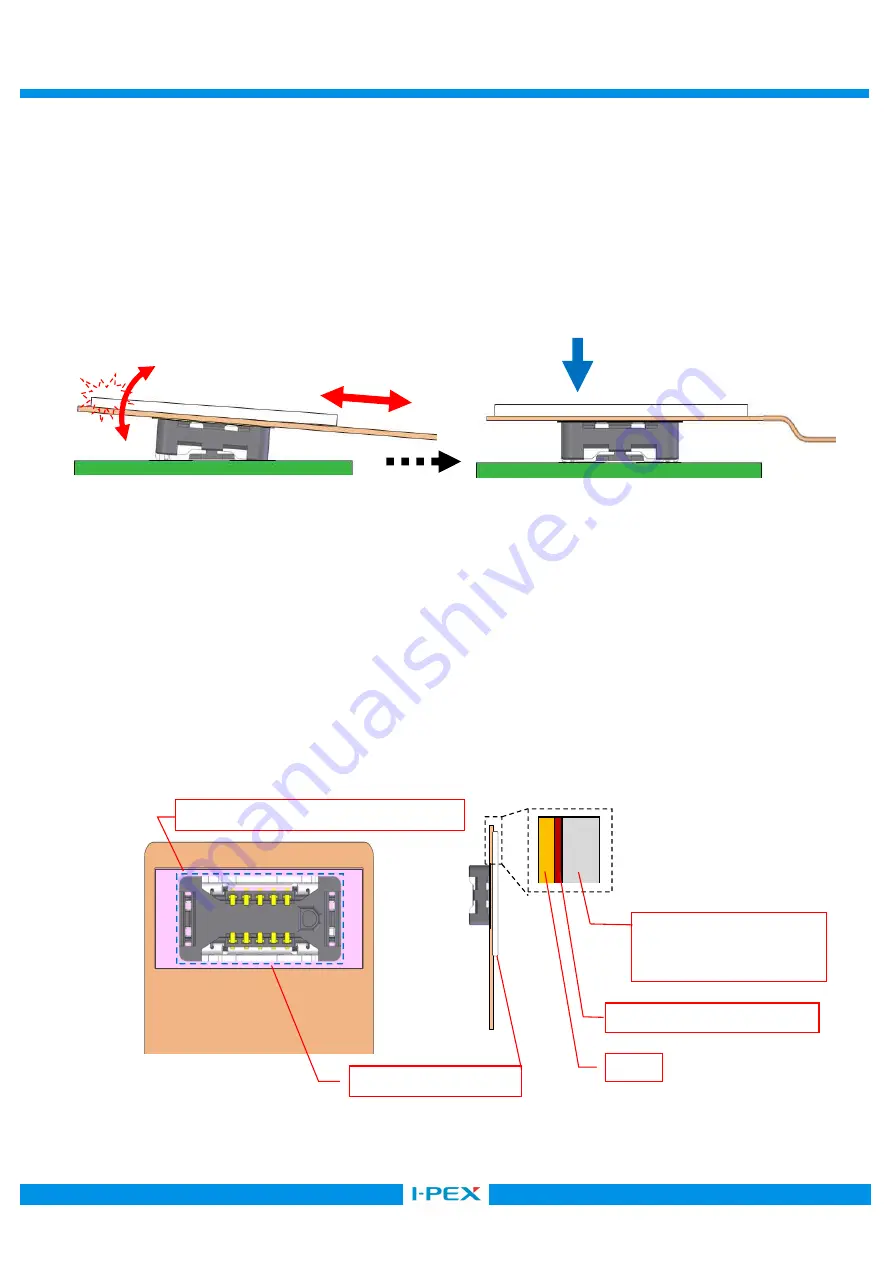
        ①FPC の取り回しによる張力や落下等の衝撃によるコネクタへの負荷対して 
            取り回しに余裕を持たせていただくことに加え、嵌合方向へ押さえつけによる保持を実施願います。 


①FPC shall not be tensed to withstand in case of a shock or a tension is applied. 

            The FPC shall be fixed toward the mating direction for the maintenance. 


②挿抜する際の FPC 側コネクタへの負荷による破損を防止するため、FPC の裏面に補強板を取り付けた状態で 

使用してください。 

補強板のサイズに関しては製品外形(パターン含む)より大きく、厚さは FPC+補強板で 0.3 mm 以上を推奨します。 


②FPC shall be used with the stiffener to prevent the connector on the FPC side from the breakage during 

insertion and extraction.


Recommended stiffener size: Larger than the connector external shape including footprint pattern. 
Recommended thickness of the FPC and a stiffener: Thicker than 0.3 mm or more. 


製品外形/ connector external shape 

保持/ fix 

FPC 取り回しの余裕 
Lay FPC with margin. 

補強板/Stiffener 

補強板  /Stiffener 

FR-4: Min. 0.3 mm 

SUS: Min. 0.2mm 

接着層  /Adhesive line 

FPC 

張力/ tension 

衝撃/ Shock 

Summary of Contents for NOVASTACK 35-HDN

Page 1: ...ASTACK 35 HDN Part No PLUG 20864 0 E 01 RECEPTACLE 20865 0 E 0 Instruction Manual 2 S19630 December 12 2019 R Shioya T Yayoshi Y Shimada 1 S19307 May 20 2019 R Shioya Y Baba Y Shimada 0 S18253 April 1...

Page 2: ...tions to handle NOVASTACK 35 HDN connector properly 1 Connector Name Part number Part name 1 1 Plug connector Product Name NOVASTACK 35 HDN Plug Ass y Part No 20864 0 E 01 1 2 Receptacle connector Pro...

Page 3: ...g direction of the connectors 2 Mounting 2 1 The recommended pattern dimensions are shown in the product drawing 2 2 The recommended metal mask thickness and opening area ratio 20864 plug 20865 recept...

Page 4: ...Profile 2 5 Hand Soldering Housing 350 3 Do not apply flux when soldering by hands The flux might rise inside the connector or it may scatter The tip of the soldering iron must not touch the connecto...

Page 5: ...irection for the maintenance FPC FPC FPC 0 3 mm FPC shall be used with the stiffener to prevent the connector on the FPC side from the breakage during insertion and extraction Recommended stiffener si...

Page 6: ...here spacers will also help to prevent the damage to the connectors and to the soldered area which might have been caused by the too large printed circuit board or unbalanced shape printed circuit boa...

Page 7: ...ad which a connector can apply press the entire upper surface of the connector with the load calculated in below formula Maximum Press load number of pin 1 0N or under 4 Mating and Unmating 4 1 Always...

Page 8: ...Caution 2 10 10 At starting the insertion please keep the slant 10 or less in direction of depth By inserting with the slant more than 10 deformation of the connector will occur 3 Caution 3 Pressing...

Reviews: