background image


NOVASTACK

®

 35-HDN    Instruction Manual


Document No. 

HIM-18019


6

  / 

8


Confidential C                                                                   

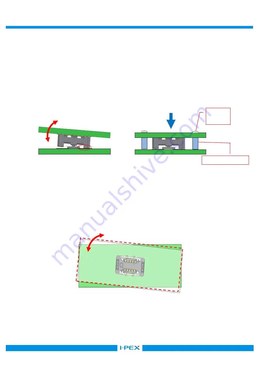
    3-2.  基板-基板での使用の場合/ Using for board to board connection. 
        ①使用される嵌合基板のサイズ・形状によってはコネクタ及びコネクタ半田部への直接負荷による破損 
            もしくは、振動・衝撃等による嵌合の傾き及び脱落が発生する可能性があります。 
            コネクタ破壊及び嵌合傾き、脱落を防止するために、スペーサー等を使用した基板間固定を推奨します。 
          ①To prevent the accidental removal or slant mating, spacers are recommended to fix the space in between 
              the two printed circuit board. There spacers will also help to prevent the damage to the connectors   
              and to the soldered area which might have been caused by the too large printed circuit board 

  or unbalanced shape printed circuit board. 


      ②基板をネジ止めにより固定する場合は、コネクタを回転させないようご注意ください。 
          回転させた状態で固定された場合、コネクタを損傷させる可能性があります。 

 
      ②Do not turn around the connector on the printed circuit board in case of using a screw. 
          If the printed circuit boards were fixed in a wrong position, the connectors may get damaged. 


ネジ止め 

/ screw 

嵌合の傾き及び脱落/ fallen or tilt 

半田部への負荷 

Load on soldering area 

コネクタの回転  / Rotated connector 

スペーサー/ Spacer 

Summary of Contents for NOVASTACK 35-HDN

Page 1: ...ASTACK 35 HDN Part No PLUG 20864 0 E 01 RECEPTACLE 20865 0 E 0 Instruction Manual 2 S19630 December 12 2019 R Shioya T Yayoshi Y Shimada 1 S19307 May 20 2019 R Shioya Y Baba Y Shimada 0 S18253 April 1...

Page 2: ...tions to handle NOVASTACK 35 HDN connector properly 1 Connector Name Part number Part name 1 1 Plug connector Product Name NOVASTACK 35 HDN Plug Ass y Part No 20864 0 E 01 1 2 Receptacle connector Pro...

Page 3: ...g direction of the connectors 2 Mounting 2 1 The recommended pattern dimensions are shown in the product drawing 2 2 The recommended metal mask thickness and opening area ratio 20864 plug 20865 recept...

Page 4: ...Profile 2 5 Hand Soldering Housing 350 3 Do not apply flux when soldering by hands The flux might rise inside the connector or it may scatter The tip of the soldering iron must not touch the connecto...

Page 5: ...irection for the maintenance FPC FPC FPC 0 3 mm FPC shall be used with the stiffener to prevent the connector on the FPC side from the breakage during insertion and extraction Recommended stiffener si...

Page 6: ...here spacers will also help to prevent the damage to the connectors and to the soldered area which might have been caused by the too large printed circuit board or unbalanced shape printed circuit boa...

Page 7: ...ad which a connector can apply press the entire upper surface of the connector with the load calculated in below formula Maximum Press load number of pin 1 0N or under 4 Mating and Unmating 4 1 Always...

Page 8: ...Caution 2 10 10 At starting the insertion please keep the slant 10 or less in direction of depth By inserting with the slant more than 10 deformation of the connector will occur 3 Caution 3 Pressing...

Reviews: