background image


NOVASTACK

®

 35-HDN    Instruction Manual


Document No. 

HIM-18019


7

  / 

8


Confidential C                                                                   

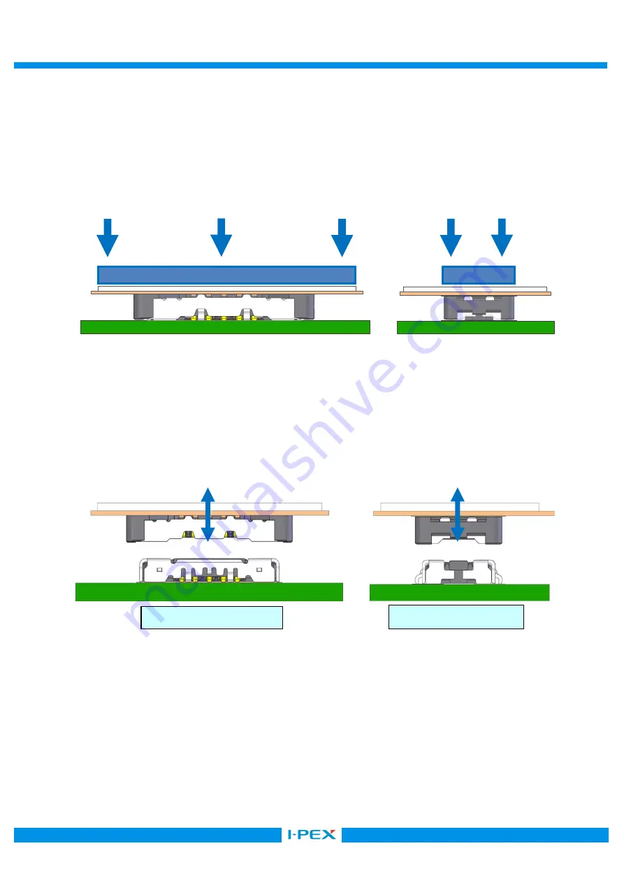
      3-3.  コネクタ抜け止め荷重/Press load 
              嵌合状態のコネクタ抜け止め荷重(筐体で押さえる荷重)につきましては下記条件でコネクタ上面全体を 
              押さえるようにしてください。 
              (抜け止め荷重:芯数×1.0N  以下) 
              To prevent the coming off of the mated connectors (the load which a connector can apply), press   
              the entire upper surface of the connector with the load calculated in below formula. 
                (Maximum Press load:  number of pin×1.0N or under) 


    4.挿抜方法/ Mating and Unmating 

 
      4 -1.  挿抜はコネクタに対して水平に行い、コネクタ破損の要因となりますので、 
                過度なこじり及び回転を加えた挿抜は行わないでください。 

 
                Always mate and unmate the connectors horizontally. An excessive twisting or   
                slanting when mating and unmating will damage the connectors. 


水平方向/ Horizontally 

奥行き方向/ Side view 

Summary of Contents for NOVASTACK 35-HDN

Page 1: ...ASTACK 35 HDN Part No PLUG 20864 0 E 01 RECEPTACLE 20865 0 E 0 Instruction Manual 2 S19630 December 12 2019 R Shioya T Yayoshi Y Shimada 1 S19307 May 20 2019 R Shioya Y Baba Y Shimada 0 S18253 April 1...

Page 2: ...tions to handle NOVASTACK 35 HDN connector properly 1 Connector Name Part number Part name 1 1 Plug connector Product Name NOVASTACK 35 HDN Plug Ass y Part No 20864 0 E 01 1 2 Receptacle connector Pro...

Page 3: ...g direction of the connectors 2 Mounting 2 1 The recommended pattern dimensions are shown in the product drawing 2 2 The recommended metal mask thickness and opening area ratio 20864 plug 20865 recept...

Page 4: ...Profile 2 5 Hand Soldering Housing 350 3 Do not apply flux when soldering by hands The flux might rise inside the connector or it may scatter The tip of the soldering iron must not touch the connecto...

Page 5: ...irection for the maintenance FPC FPC FPC 0 3 mm FPC shall be used with the stiffener to prevent the connector on the FPC side from the breakage during insertion and extraction Recommended stiffener si...

Page 6: ...here spacers will also help to prevent the damage to the connectors and to the soldered area which might have been caused by the too large printed circuit board or unbalanced shape printed circuit boa...

Page 7: ...ad which a connector can apply press the entire upper surface of the connector with the load calculated in below formula Maximum Press load number of pin 1 0N or under 4 Mating and Unmating 4 1 Always...

Page 8: ...Caution 2 10 10 At starting the insertion please keep the slant 10 or less in direction of depth By inserting with the slant more than 10 deformation of the connector will occur 3 Caution 3 Pressing...

Reviews: