background image


NOVASTACK

®

 35-HDN    Instruction Manual


Document No. 

HIM-18019


8

  / 

8


Confidential C                                                                   

        4-2.  注意事項/ Cautions


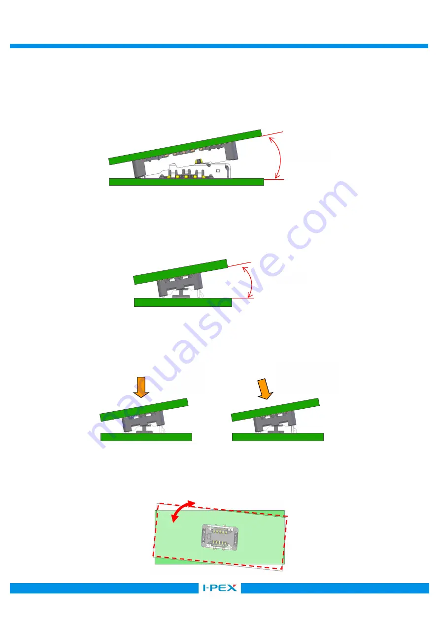
        [注意 1/Caution 1] 
            挿入開始時の水平方向のこじり角度は、10°以下でお願い致します。 

            10°以上での挿入は、コネクタ変形の原因となります。 

              Insertion angle shall not be slanted more than 10 degrees. 

                Slanted degree over 10 degrees may cause the deformation of the connector. 


      [注意 2/Caution 2]


            挿入開始時の奥行き方向のこじり角度は、10°以下でお願いします。 

            10°以上での挿入は、コネクタ変形の原因となります。 

            At starting the insertion, please keep the slant 10 ° or less in direction of depth. 

            By inserting with the slant more than 10°, deformation of the connector will occur. 


      [注意 3/Caution 3] 
            斜めに挿入された場合でも、上面より真直ぐに押せば、コネクタのガイド機能により姿勢が安定致します。 

            斜め方向からの無理な挿入は行わないで下さい。 

            Pressing straight from upper side, the posture becomes stable by guide function of connector. 

            Do not insert forcedly from oblique direction. 


      [注意 4/Caution 4] 
        回転を加えた状態での挿抜は行わないでください。 


  Do not mate or unmate when the connector is turned around. 


コネクタの回転/ Rotated connector 

10°  MAX 

10°  MAX 

Pass 

Fail 

Summary of Contents for NOVASTACK 35-HDN

Page 1: ...ASTACK 35 HDN Part No PLUG 20864 0 E 01 RECEPTACLE 20865 0 E 0 Instruction Manual 2 S19630 December 12 2019 R Shioya T Yayoshi Y Shimada 1 S19307 May 20 2019 R Shioya Y Baba Y Shimada 0 S18253 April 1...

Page 2: ...tions to handle NOVASTACK 35 HDN connector properly 1 Connector Name Part number Part name 1 1 Plug connector Product Name NOVASTACK 35 HDN Plug Ass y Part No 20864 0 E 01 1 2 Receptacle connector Pro...

Page 3: ...g direction of the connectors 2 Mounting 2 1 The recommended pattern dimensions are shown in the product drawing 2 2 The recommended metal mask thickness and opening area ratio 20864 plug 20865 recept...

Page 4: ...Profile 2 5 Hand Soldering Housing 350 3 Do not apply flux when soldering by hands The flux might rise inside the connector or it may scatter The tip of the soldering iron must not touch the connecto...

Page 5: ...irection for the maintenance FPC FPC FPC 0 3 mm FPC shall be used with the stiffener to prevent the connector on the FPC side from the breakage during insertion and extraction Recommended stiffener si...

Page 6: ...here spacers will also help to prevent the damage to the connectors and to the soldered area which might have been caused by the too large printed circuit board or unbalanced shape printed circuit boa...

Page 7: ...ad which a connector can apply press the entire upper surface of the connector with the load calculated in below formula Maximum Press load number of pin 1 0N or under 4 Mating and Unmating 4 1 Always...

Page 8: ...Caution 2 10 10 At starting the insertion please keep the slant 10 or less in direction of depth By inserting with the slant more than 10 deformation of the connector will occur 3 Caution 3 Pressing...

Reviews: